


Premier 48-W Quick Start Guide
INS531
13
6. Attributes & Operation Modes
Polling
Polling occurs between the devices and the receiver at a pre-
determined interval of 15 minutes. This helps to conserve battery
life. Poll intervals are set to 4 minutes when the system is in
Commission Mode. (see page 14). The standard poll time is not
adjustable. If the system is powered down for more than 1 hour, the
devices will go into an Offline Mode to conserve battery life, in this
case it can take up to 2 hours for all devices to come back online,
alternatively each device should have its tamper circuit opened to
force communications. When forcing the devices to come back
online the same setup principles should be used and devices
closest to the receiver should be activated first, this will again allow
the mesh network to be established.
System Devices
Auto Mode
Auto Mode is the default device setting for the
Prestige XT-W QD-W
,
and should be used for all devices where possible. When in Auto
Mode, devices poll at 15 minute intervals. Following activation,
devices will not transmit the same activation again for a period of 3
minutes.
Always Awake
This mode should only be used on devices which are required to
signal at all times and is the default setting for the
Impaq Contact-W
and
Impaq Plus-W
. For example a
Impaq Contac-W
on a door
which you need to know is opened, regardless of system state; or
devices such as PA buttons & smoke detectors which have been
connected to the inputs of the Magnetic Contact. The number of
devices on a system in this mode should be kept to a minimum.
As this is a dynamic bi-directional system any device which is
Always Awake has the capability to shorten the battery life of
other devices. Please see the Battery Considerations section on
page 14
Impaq Contact-W
The
Impaq Contact-W
has 3 additional inputs labelled MAG 1 COM
MAG 2; these inputs can be used for any N/C device. If the Reed
switch is disabled the device can be used as a transmitter for any
device wired into one of the two inputs.
The two additional inputs are NOT independently programmable of
the reed switch, when mapped to a panel zone if either the reed
switch or any of the inputs are triggered the zone which the device
is mapped too will go active.
Switch 3
on the expander controls how MAG 2/COM reports to the
control panel. By default the switch is on and anything connected to
MAG 2/COM will report as a tamper. When switch 3 is OFF MAG
2/COM will report as alarm.
In the case of the
Impaq Contact –W
being used to trigger 24 hour
circuits, or where the zone is required to chime, the device attributes
should be changed to Always Awake as detailed previously.
The two additional inputs may also be used to transmit N/C signals
from any other locally powered or self powered device, depending
on the type of device used you should choose the device attributes
to suit.
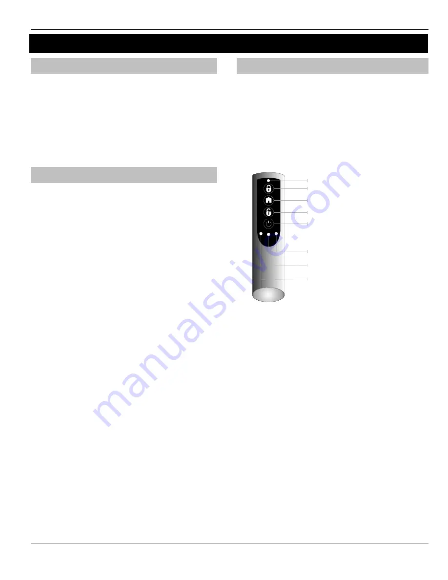
Premier SmartKey™
LED Indications
Premier SmartKey
™ Status LED
The Status LED has four colours. This LED cannot be disabled.
1.
Pink = Power Up or Down
2.
Green = Successful communication with the system
3.
Flashing Blue = communication with system.
4.
Red = Out of Range
5.
Turquoise = Function Mode
PA Activation
By default PA activation is enabled on the
Premier SmartKey™
;
however the control panel should be programmed to enable Radio
PA. Please refer to your Control Panel manual for details.
Enable/Disable Alarm Status LED’s
The Alarm Status LED’s can be enabled or disabled either from the
Engineers Keypad (see page 10), or
RICOCHET™ Monitor
.
Auxiliary Functions
The
Premier SmartKey™
can also be used to activate auxiliary
devices from the control panel outputs. The function keys should first
be enabled either from the Engineers Keypad (see page 10), or
RICOCHET™ Monitor
. Once enabled the user can enter Auxiliary
mode by pressing the power button when the
SmartKey™
is powered
up, the status LED will change from blue to turquoise to indicate
Function mode.
Once enabled the outputs should be programmed in the control panel
to activate the desired function. Please refer to the Control Panel
manual for details on how to programme the outputs.
Instant Disarm
Pressing the DISARM button without powering up the
Premier
SmartKey
™ will disarm the system, or all areas allocated to the user,
whilst the disarming process is taking place the alarm status LED’s will
change from the ARMED to the DISARMED state.
POWE R
FUNC TION 1/PC C ontrol 1
FUNC TION 3/PC C ontrol 3
FUNC TION 2/PC C ontrol 2
Function S tatus LE D’s
P remier S martKey status LE D
FUNC TION 3
FUNC TION 2
FUNC TION 1
Содержание Premier Elite 48-W
Страница 1: ...INS531 Premier 48 W Quick Start Guide...
Страница 18: ...Premier 48 W Quick Start Guide 18 INS531 Notes...
Страница 19: ...Premier 48 W Quick Start Guide INS531 19 Notes...


