background image

6 Using the product 


57


[Options]


Draught measure start/stop

: The draught 

measurement can be started and ended during a measurement. 

5.


6.2.6.


CO undiluted 

Calling up the function: 

✓ 

A multi-hole probe (0554 5762) must be connected. 

 [ ] 


Measurements 


[OK]


CO undiluted 


[OK]

.


Performing the measurement: 

1.


Start measurement: 

[

]


-  The reading is displayed. 

2.


Quit measurement: 

[

]


Options: 

>

 [Options] 


Clipboard

: Data are saved to the clipboard. 

[Options] 

 Delete clipboard

: Any data saved to the clipboard 

is deleted. 

>

 [Options] 


Save

: The readings are saved in a record. 

[Options] 


Show Graphic

: The readings are displayed in 

form of a line graph. 


6.2.7.


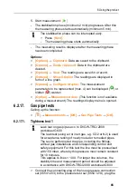
Smoke No. / HCT 

Calling up the function: 

 [ ] 


Measurements 


[OK]


Smoke No. / HCT 


[OK]


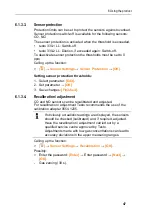
The parameters 

Smoke No.

 and 

Oil derivatives

 are only 

available for oil fuels. 


Determining smoke tester no. / smoke nos. / oil derivative with 
the smoke pump and entering manually: 

1.


Select parameter 


[Edit]

.  

2.


Enter data or values 


[Next] 

or 

[OK]

Determining smoke tester no. / smoke nos. / oil derivative with 
the smoke tester testo 308 and transferring wireless: 

-  The testo 308 must be in data transfer mode (

 lights up). 

[Options] 


t308

-  The values recorded by the smoke tester are transferred to the 

testo 330. 

Содержание 330

Страница 1: ...testo 330 Flue gas analyzer Instruction manual ...

Страница 2: ...2 ...

Страница 3: ...ion 18 4 1 Case 0516 3300 accessory 18 4 1 1 Bottom level view 18 4 1 2 Top level view 19 4 2 Case 0516 3301 accessory 20 4 2 1 Bottom level view 20 4 2 2 Middle level view 21 4 2 3 Top level view 22 4 3 Measuring instrument 23 4 3 1 Overview 23 4 3 2 Keypad 24 4 3 3 Display 25 4 3 4 Device connections 26 4 3 5 Interfaces 26 4 3 6 Components 27 4 3 7 Carrying strap 0440 1001 28 4 4 Modular flue ga...

Страница 4: ...4 6 1 2 3 Bluetooth 44 6 1 2 4 Language 44 6 1 2 5 Country version 45 6 1 2 6 Password protection 45 6 1 3 Sensor settings 46 6 1 3 1 NO2 addition 46 6 1 3 2 O2 reference 46 6 1 3 3 Sensor protection 47 6 1 3 4 Recalibration adjustment 47 6 1 4 Fuels 48 6 1 5 Programs 49 6 2 Measuring 50 6 2 1 Preparing for measurement 50 6 2 1 1 Zeroing phases 50 6 2 1 2 Using the modular flue gas probe 51 6 2 1 ...

Страница 5: ...7 Maintaining the product 70 7 1 Cleaning the measuring instrument 70 7 2 Replacing sensors 70 7 3 Recalibrating adjusting sensors 71 7 4 Replacing additional filter 71 7 5 Cleaning the modular flue gas probe 72 7 6 Replacing the probe module 72 7 7 Changing the thermocouple 72 7 8 Condensate container 74 7 9 Checking replacing the particle filter 75 8 Tips and assistance 76 8 1 Questions and answ...

Страница 6: ...at you can refer to it when necessary Hand this documentation on to any subsequent users of the product Symbols and writing standards Representation Explanation Warning advice risk level according to the signal word Warning Serious physical injury may occur Caution Minor physical injury or damage to the equipment may occur Apply the specified precautionary measures Note Basic or further informatio...

Страница 7: ...k must only be carried out by authorised personnel Testo will otherwise refuse to accept responsibility for the proper functioning of the measuring instrument after repair and for the validity of certifications Only use the device in closed dry rooms and protect it from rain and moisture Temperatures given on probes sensors relate only to the measuring range of the sensors Do not expose handles an...

Страница 8: ...the responsible approval authority may cause the retraction of the type approval Data transfer may be disturbed by equipment that uses the same ISM band e g WLAN microwave ovens ZigBee The use of radio communication links is not permitted among others in aeroplanes and hospitals For this reason the following points must be ensured before entering Switch off the device Isolate the device from any e...

Страница 9: ...ng and optimising the flow and return temperatures of heating systems CO and CO2 environment measurement Detection of CH4 methane and C3H8 propane The testo 330 can be used for measurements on CHP stations in accordance with the first German Federal Immission Control Ordinance BImschV In principal the CO sensor can also be used for measurements on CHP stations If you should carry out more than 50 ...

Страница 10: ...ese regulations and prerequisites for use and acknowledges that the re sale export import etc in particular in countries without wireless permits is his responsibility 3 2 Technical data 3 2 1 Examinations and licenses As declared in the certificate of conformity this product complies with Directive 2014 30 EC 3 2 2 Bluetooth module option 3 2 2 1 Bluetooth Type BlueGiga valid to serial number 267...

Страница 11: ... FCC guidelines Commissioning is subject to the two following conditions 1 This device must not generate any dangerous interferences and 2 this device must be able to receive interferences even if these could have undesired effect on the operation Changes The FCC demands that the user is to be informed that with any changes and modifications to the device which have not been explicitly approved by...

Страница 12: ...oved EN50379 1 2 3 VDI4206 1 IC Warnings This instrument complies with Part 15B of the FCC Rules and Industry Canada RSS 210 revision 8 Commissioning is subject to the following two conditions 1 This instrument must not cause any harmful interference and 2 this instrument must be able to cope with interference even if this has undesirable effects on operation Cet appareil satisfait à la partie 15B...

Страница 13: ... encouraged to try to correct the interference by one or more of the following measures Reorient or relocate the receiving antenna Increase the separation between the equipment and receiver Connect the equipment into an outlet on a circuit different from that to which the receiver is connected Consult the dealer or an experienced radio TV technician for help Caution Changes or modifications not ex...

Страница 14: ... 0632 3331 0 500 ppm 1 ppm NO 0 3000 ppm 1 ppm NOlow 0 300 ppm 0 1 ppm Draught 9 99 40 hPa 0 01 hPa P 0 300 hPa 0 1 hPa Temperature 40 1200 C 0 1 C 40 0 999 9 C 1 C rest of range Efficiency net 0 120 0 1 Flue gas loss 0 99 9 0 1 AmbCO2 with probe 0632 1240 0 1 vol 0 10000 ppm Gas leak testing with probe 0632 3330 0 10000 ppm CH4 C3H8 1 above the sensor protection threshold Resolution 1 ppm up to m...

Страница 15: ... 5 of mv rest of range 40s t90 AmbCO through flue gas probe 10 ppm 0 100 ppm 10 of mv 101 2000 ppm 35s t90 AmbCO with 0632 3331 5 ppm 0 100 ppm 3 5 of mv 101 ppm approx 35s t90 NO 2 ppm 0 39 9 ppm 5 of mv 40 2000 ppm 10 of mv 2001 3000 ppm 30s t90 NOlow 2 ppm 0 39 9 ppm 5 of mv rest of range 30s t90 Draught 4 0 02 ppm or 5 of mv2 0 50 0 60 hPa 0 03 hPa 0 61 3 00 hPa 1 5 of mv 3 01 40 00 hPa 2 high...

Страница 16: ...pprox 35s t90 Gas leak testing with 0632 3330 2s t90 3 2 6 Other instrument data Flue gas analyser Characteristic Values Storage and transport temperature 20 50 C Operating temperature 5 45 C Ambient humidity 0 90 rH not condensing Power supply Battery 3 7 V 2 6 Ah Mains unit 6 V 1 2 A Protection class IP40 Weight 600 g excluding battery Dimensions 270 x 90 x 65 mm Memory 500 000 readings Display ...

Страница 17: ...ttery charge time approx 5 6 h Battery operation time 6h pump on 20 C ambient temperature Bluetooth option Range 10 m Warranty Measuring instrument 48 months LL sensors O2 CO 48 months NOlow sensor 12 months Other sensors 24 months Flue gas probe 48 months Thermocouple 12 months Battery 12 months Further warranty terms see website www testo com warranty ...

Страница 18: ...essory Recommended for stowing away the measuring instrument and accessories example 4 1 1 Bottom level view 1 Sealing clip 2 testo 330 1 2 LL flue gas analyzer 3 Repository for printer accessories Spare batteries for IRDA printer 1 roll of spare thermal paper 0554 0568 ...

Страница 19: ...0600 9741 Pitot tube for heating check 0635 2050 8 Large storage compartment Mains unit for testo 330 1 2 LL 0554 1096 Differential temperature set 0554 1208 Spare dirt filter 0554 0040 9 Round storage compartment Hose connection set with pressure adapter 0554 1203 4 1 2 Top level view 1 Soot pump set 0554 0307 2 Storage compartment Fine pressure probe 0638 0330 ...

Страница 20: ...e for surface probe 0430 1215 4 Combustion air temperature probe 0600 9787 5 Surface temperature probe Type K 0604 0994 4 2 Case 0516 3301 accessory Recommended for stowing away the measuring instrument and accessories example 4 2 1 Bottom level view 1 Fine pressure probe 0638 0330 2 testo 308 smoke tester 0632 0308 ...

Страница 21: ...zer 3 Repository for printer accessories Spare batteries for IRDA printer 1 roll of spare thermal paper 0554 0568 4 Repository for printer IRDA printer 0554 0549 Bluetooth IRDA printer 0554 0620 5 Instruction manual 6 Lock 7 Probes Flue gas probe e g 0600 9741 Pitot tube for heating check 0635 2050 ...

Страница 22: ...age compartment Hose connection set with pressure adapter 0554 1203 4 2 3 Top level view 1 Soot pump set 0554 0307 2 Storage compartment Fine pressure probe 0638 0330 3 Storage compartment Capillary hose set for fine pressure probe 0554 1215 Connecting cable for surface probe 0430 1215 4 Combustion air temperature probe 0600 9787 5 Surface temperature probe Type K 0604 0994 ...

Страница 23: ...nstrument 4 3 1 Overview 1 Switch on off 2 Interfaces USB PS2 infrared CAUTION Risk of injury from infrared beam Do not direct infrared beam at human eyes 3 Condensate trap on rear 4 Fixing eyelets for carrying strap left and right 5 Display ...

Страница 24: ...aged by the effects of magnetism e g monitors computers or credit cards 7 Keypad 8 Service cover on rear 9 Gas outlet 10 Unit connections flue gas probe sensor pressure probe mains unit 4 3 2 Keypad Key Functions Switch measuring instrument on off OK Example Function key orange 3x relevant function is shown on the display Scroll up increase value Scroll down reduce value esc Back cancel function O...

Страница 25: ...re blue symbol Bluetooth on grey symbol Bluetooth off Battery operation Indication of remaining capacity of the rech batt by colour and filling degree of the battery symbol green 5 100 red 5 Mains operation Indication of remaining capacity of battery see above 2 Info field of register tabs Indication of selected Address Location chosen fuel chosen measurement type 3 Selection field for functions c...

Страница 26: ...scription 26 4 3 4 Device connections 1 Probe socket 2 Flue gas socket 3 Mains unit socket 4 Pressure socket 4 3 5 Interfaces 1 USB interface 2 PS2 interface 3 Infrared interface IrDA 4 Bluetooth interface optional ...

Страница 27: ...4 Product description 27 4 3 6 Components 1 Rechargeable battery 2 Measuring gas pump 3 Slot for CO sensor or COlow sensor 4 Slot O2 sensor 5 Slot NO sensor or NOlow sensor 6 Additional filter ...

Страница 28: ...ts front 2 Pick the service cover up at the markings arrows using your index finger and thumb and press gently to release the lock 3 Fold up the service cover and remove it 4 Secure the sealing caps in the two holders on the inside of the service cover 1 5 Attach the service cover and engage it in place Engage the carrying strap clip in the fixing eyelets on the sides of the device Note the guide ...

Страница 29: ...ription 29 4 4 Modular flue gas probe 1 Removable filter chamber with window and particle filter 2 Probe handle 3 Connecting cable 4 Connector plug for measuring instrument 5 Probe module lock release 6 Probe module ...

Страница 30: ...ocket via the mains unit The instrument must be switched off Change the rechargeable battery within 3 minutes so that device settings e g date time are not lost 1 Place the measuring instrument on its front 2 Remove the service cover Take hold of it at the markings arrows using the index finger and thumb press slightly fold up and remove 3 Open the battery lock Press the grey key and push in direc...

Страница 31: ...below 0 C best storage conditions with a charge level of 50 80 at an ambient temperature of 10 20 C recharge completely before use For longer breaks you should discharge and recharge the batteries every 3 months Trickle charging should not exceed 2 days 5 2 1 3 Mains operation 1 Connect the plug of the mains unit to the mains unit socket on the measuring instrument 2 Connect the mains plug of the ...

Страница 32: ... start sensor detection manually after changing the probe Options Sensor detection Connecting flue gas probes gas pressure adapters temperature adapters Insert the connector plug into the flue gas socket and lock by slightly turning it clockwise bayonet lock There must be no more than one extension lead 0554 1202 between measuring instrument and flue gas probe Connecting other sensors Insert the c...

Страница 33: ...t function The chosen function appears in a frame 2 Confirm selection OK The chosen function is opened 5 2 5 Entering values Some functions require values numbers units characters to be entered Depending on the function that is chosen the values are entered via either a list field or an input editor List field 1 Select the value to be changed numerical value unit depending on the selected function...

Страница 34: ...Ι ABC Ι ABC Position the cursor in the text Select Ι ABC Ι Ι or Ι Delete character before or after the cursor Select next or 3 Repeat steps 1 and 2 as required 4 Save the entry Select next Next 5 2 6 Show graphic 1 Current measuring value 2 End time of the displayed period The time is not displayed if no measuring value was recorded for this period ...

Страница 35: ...e clipboard measuring results from various measurement types can be combined to a common record which can then be printed out see above Data are saved to the clipboard via the menu Options and the command Clipboard If there are data in the clipboard the status bar shows the symbol If there are data in the clipboard and the command Print is triggered all data in the clipboard will be printed out On...

Страница 36: ...e deleted Call up function Address Location OK There are various options for opening address 1 Edit search setting Edit 2 Select search setting OK Possible settings Show all All address location are displayed Search A search text only brings up address location that contain characteristics of the search text Filter Individual letters or numbers can be selected All data beginning with the relevant ...

Страница 37: ...1 Edit search criteria Edit 2 Select search criteria OK Possible options Contact person Address Town city Postcode Street The selected criterion is displayed 3 Enable tab 4 Select the required tab and sometimes Filter The search result for the relevant letter or number is displayed Create a new measuring location A location is always created under an address 1 Select the address in which the locat...

Страница 38: ...address delete an existing folder including the locations created therein Delete All addresses delete all existing folders including the locations created in them 5 4 Measurement records Calling up the function Measurement Records OK There are various options for opening protocols see Address Location page 36 Displaying a record 1 Choose the required record from the detailed view 2 Print Data Prin...

Страница 39: ...or i Carrying out a gas path check testo 330 2 LL 1 Gas Path Check OK 2 Place the black sealing cap on the tip of the flue gas probe The pump flow is displayed If the volumetric flow rate is less than 0 02 l min the gas paths are not leaking 3 End of check OK Viewing device errors Error Diagnosis OK Unrectified errors are displayed View next previous error View sensor diagnosis 1 Sensor Diagnosis ...

Страница 40: ...ollowing functions are available 3 Assign the selected function to the right function key Press Config Key 6 1 2 Instrument settings It is assumed that the contents of the chapter First steps see First steps page 30 are known Calling up a function Device Settings 6 1 2 1 Readings display The parameters units and the display representation number of readings displayed per display page can be set Th...

Страница 41: ...on of the heat value range qAgr Flue gas loss under due consideration of the heat value range η Efficiency under due consideration of the heat value range η Efficiency without consideration of the heat value range Dew a Flue gas dew point temperature Calling up the function Instrument Settings OK Readings Display OK Changing parameter unit in a line 1 Select the line where you want to position the...

Страница 42: ... up the function Instrument Settings OK Alarm Limits OK Switching alarm signals on off changing alarm limits 1 Select function or parameter Edit 2 Set parameter and partly OK 3 Save changes Finished Reset the enabled value to the factory setting Standard 6 1 2 3 Units The units used for parameters in configuration menus can be set Calling up the function Instrument Settings OK Units OK Adjustable ...

Страница 43: ...rameter and partly OK 3 Save changes Finished 6 1 2 6 Display brightness The intensity of the display illumination can be set Calling up the function Instrument Settings OK Display Brightness OK Performing settings Set parameter OK 6 1 2 1 Choose measurement type Individual measurement types can be shown or hidden These are displayed or hidden accordingly under Measurement options Call up function...

Страница 44: ...lect function Edit Enter values for Line 1 Line 2 Line 3 and the Footnote Print out system data and or customer data 3 Save the entry select Finished 6 1 2 3 Bluetooth This menu is only available if the instrument is equipped with Bluetooth The Bluetooth module can be switched on off The relay can now be tested Calling up the function Instrument Settings OK Bluetooth Edit Making settings Set param...

Страница 45: ...an be password protected A password is specified in the menu Password Protection see Password protection page 45 Possibly Enter the password Enter Enter password Next OK Setting the country version 1 Select the country version OK 2 Confirm the confirmation request Yes OK The system is restarted 6 1 2 6 Password protection The password protection is only valid for functions identified by the follow...

Страница 46: ...d see Password protection page 45 Calling up the function Sensor Settings NO2 Addition Edit Possibly Enter the password Enter Enter password Next OK Setting the NO2 addition Set parameter OK 6 1 3 2 O2 reference The O2 reference value can be set The setting of the O2 reference value can be password protected see Password protection page 45 Calling up the function Sensor Settings O2 Reference Edit ...

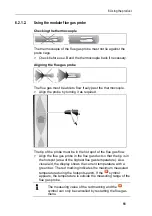
Страница 47: ...resholds 1 Select parameter Edit 2 Set parameter OK 3 Save changes Finished 6 1 3 4 Recalibration adjustment CO and NO sensors can be recalibrated and adjusted For recalibration adjustment Testo recommends the use of the calibration adapter 0554 1205 If obviously unrealistic readings are displayed the sensors should be checked calibrated and if required adjusted Have the recalibration adjustment c...

Страница 48: ...tual value is stable adjustment OK or Abort no adjustment esc 8 Save changes Finished 6 1 4 Fuels The fuel can be selected The fuel specific coefficients and limits can be set Apart from the pre configured fuels 10 more customer specific fuels can be configured Fuel parameter see www testo com download center registration required In order to maintain the measuring accuracy of the instrument one m...

Страница 49: ...ing programs serve the purpose of saving and representing measuring sequences After the end of the measuring process the readings of a measuring program are automatically saved in a record Only one measuring program can be activated in the instrument Calling up the function Programs OK Activating deactivating a program Select the program Enable or Disable When activating a program The program is a...

Страница 50: ... during the zeroing phase If a combustion air temperature probe is connected the combustion air temperature is measured continuously via this probe Gas zeroing When the instrument is switched on the measurement menu is opened and the gas sensors are zeroed testo 330 1 LL The flue gas probe must be in the open air during the zeroing phase testo 330 2 LL The flue gas probe can be in the flue gas duc...

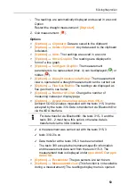
Страница 51: ...red The tip of the probe must be in the hot spot of the flue gas flow Align the flue gas probe in the flue gas duct so that the tip is in the hotspot area of the highest flue gas temperature As a visual aid the display shows the current temperature with a green bar The red marking indicates the maximum measured temperature during the hotspot search If the symbol appears the temperature is outside ...

Страница 52: ...ment results the measurement period of a flue gas measurement should be approx 3 min and the measuring instrument should display stable measured values Calling up the function 1 Measurements OK Flue Gas OK 2 Select the fuel OK Performing the measurement 1 Start measurement If a separate measurement of CO undiluted has not yet been carried out this value is calculated using the readings of the flue...

Страница 53: ... matrix see below Options Number of Lines Change the number of measuring values per display page Options Accept measuring values from 315 3 Ambient CO CO2 values measured with the testo 315 3 can be accepted by the testo 330 Data is transferred via Bluetooth or via the IrDA interface For data transfer via Bluetooth the testo 315 3 and the testo 330 2 must have this option otherwise data is transfe...

Страница 54: ...ne green of the flue gas matrix using the limits pre configured for each system type Options Reset Graphic The displayed graphical values are deleted Options Limits This function is not available during a measurement Enter limits to be able to configure the ideal zone green of the flue gas matrix Options CO O2 or CO CO2 Choose which parameter should be assigned to the x axis of the display matrix ...

Страница 55: ...The readings are displayed in form of a line graph Options Configure Graphic The measurement parameters to be represented max 4 can be displayed or hidden Options Measurement view This function is not available during a measurement The readings display menu is opened 4 6 2 4 Micro pressure probe The following measurements can be performed using the micro pressure probe 0638 0330 Ext Draught Ext De...

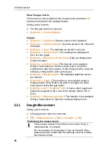
Страница 56: ...probe in the centre of flow area of the highest flue gas temperature The graphical representation of the maximum measured flue gas temperature red line helps when positioning the flue gas probe Option Start draught measurement Drgt start 3 Next The qA readings O2 AT VT and the draught value are determined 30s Option Cancel draught measurement Drgt stop The measurement stops automatically The readi...

Страница 57: ...tions Save The readings are saved in a record Options Show Graphic The readings are displayed in form of a line graph 6 2 7 Smoke No HCT Calling up the function Measurements OK Smoke No HCT OK The parameters Smoke No and Oil derivatives are only available for oil fuels Determining smoke tester no smoke nos oil derivative with the smoke pump and entering manually 1 Select parameter Edit 2 Enter dat...

Страница 58: ... Do not smoke or use naked flames during measurement Do not measure for longer than 5 min as the drift of the pressure sensor could have the effect that the readings are outside the tolerance limits The gas pressure set 0554 1203 must be connected Calling up the function Measurements OK Differential Pressure OK Performing the measurement At the start of the measurement the instrument s pressure so...

Страница 59: ...p the function Measurements OK Differential Temperature OK Performing the measurement 1 Start measurement The readings and the calculated differential temperature T1 T2 are displayed 2 Quit measurement Options Options Clipboard Data are saved to the clipboard Options Delete clipboard Any data saved to the clipboard is deleted Options Save The readings are saved in a record Options Show Graphic The...

Страница 60: ...lable if the chosen fuel is a gas Calling up the function Measurements OK Gas Flow OK Performing the measurement 1 Start measurement The measuring duration is displayed 2 When the adjusted gas flow is reached The calculated gas flow and the gas burner capacity in kW are displayed Options Options Clipboard Data are saved to the clipboard Options Delete clipboard Any data saved to the clipboard is d...

Страница 61: ... settings The unit for the oil flow can be changed kg h gal h or gal h kg h 6 2 13 CO ambient An ambient CO probe recommended or a flue gas probe must be connected Cigarette smoke influences the measurement by more than 50 ppm The breath of a smoker influences the measurement by about 5 ppm When using an ambient CO probe note that The direction of flow of the gas has an effect on the accuracy of t...

Страница 62: ...ed 6 2 14 CO2 ambient An ambient CO2 probe 0632 1240 must be connected In order to obtain correct readings it is imperative to enter the prevailing absolute pressure This can be entered directly Pressure Absolute or it is automatically calculated when entering Altitude and barometric pressure Pressure Barom Calling up the function Measurements OK CO2 Ambient OK Performing the measurement 1 Select ...

Страница 63: ...nge of data which can be read out depends on the type of the automatic furnace Calling up the function 1 Connect the readout adapter to the instrument PS2 interface and to the automatic furnace use adapter ring if necessary 2 Measurements OK Automatic Furnace OK The data are read from the automatic furnace Depending on the automatic furnace the data are updated at the latest every 30 s The values ...

Страница 64: ...has occurred last is at position 1 in the error list Options Fault Display of faults 6 2 16 Solid fuel measurement The solid fuel measurement program is only available with instruments that come with the CO sensor not COlow For measurements in accordance with the 1st Federal Immission Control Ordinance BImSchV a CO H2 compensated sensor 0393 0101 is required The function is only available if the a...

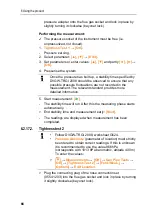
Страница 65: ...ent view This function is not available during a measurement The readings display menu is opened 6 2 17 Gas pipe tests Calling up the function Measurements OK Gas Pipe Tests OK 6 2 17 1 Tightness test 1 Leak test on gas pipes acc to DVGW TRGI 2008 worksheet G600 The leak test using air or inert gas e g CO2 or N2 is used for acceptance testing of newly routed or remedied pipes The test is performed...

Страница 66: ...dard provides more detailed information 5 Start measurement The stability time will run After this the measuring phase starts automatically End stability time and measurement early Next The readings are displayed when measurement has been completed 6 2 17 2 Tightness test 2 Follow DVGW TRGI 2008 worksheet G624 Pressure Absolute parameter of location must strictly be entered to obtain correct readi...

Страница 67: ...this the measuring phase starts automatically End stability time and measurement early Next The readings and Result Tightness Test 2 are displayed when measurement has been completed 7 Edit Select test result OK 6 2 17 3 Let By Test Plug the connecting plug of the hose connection set 0554 1203 into the flue gas socket and lock in place by turning it slightly clockwise bayonet lock Performing the m...

Страница 68: ...the gas type to be detected and perform gas leak testing by following the instructions described in the documentation of the gas leak probe 1 Start detection The gas concentration is displayed if it exceeds the limit an alarm signal will sound Options Options Save the readings are saved in a record Options Show Graphic The readings are displayed in form of a line graph Options Alarm Limit This fun...

Страница 69: ...ata takes place via Print or The function is only available if a printout is possible Representation of the available characters per line is limited on the printout Thus the unit mg KWh is displayed on the printout as mg k 6 3 2 PC Pocket PC Data transfer to a PC can take place via USB IrDA or Bluetooth Data transfer to a Pocket PC can take place via IrDA or Bluetooth You must also refer to the do...

Страница 70: ...tact with solvents and or degreasers e g isopropanol in the case Evaporating or leaking solvents and or degreasers may cause damage to the instrument and to the sensors The use of strong or harsh alcohol or brake cleaner can result in damage to the instrument 7 2 Replacing sensors A slot bridge 0192 1552 must be inserted in slots which are not equipped with a sensor Used sensors must be disposed o...

Страница 71: ...ed 7 3 Recalibrating adjusting sensors See Sensor settings page 46 7 4 Replacing additional filter The additional filter provides added protection should problems occur with the particle filter in the flue gas probe The additional filter is very rarely contaminated if the measuring instrument is used normally Check the additional filter visually periodically for contamination and replace it if nec...

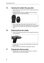
Страница 72: ...probe module and probe handle see illustration Do not use a brush 3 Fit a new probe module on the probe handle and engage it in place 7 6 Replacing the probe module Disconnect the flue gas probe from the measuring instrument prior to cleaning 1 Press the key on the top of the probe handle and remove the probe module 2 Plug in the new probe module and engage it in place 7 7 Changing the thermocoupl...

Страница 73: ...lug in head from the socket using a screwdriver and pull the thermocouple out of the probe shaft 3 Keep inserting the new thermocouple into the probe shaft until the connection head clicks into place 4 Fit a new probe module on the handle and engage in place ...

Страница 74: ...onsists of a weak mix of acids Avoid skin contact Make sure that the condensate does not run over the housing CAUTION Condensate entering the gas path Damage to sensors and flue gas pump Do not empty the condensate trap while the flue gas pump is in operation 1 Unlock the condensate trap and pull it vertically off the measuring box 2 Open the condensate outlet on the condensate trap Pull out appro...

Страница 75: ...ilter of the modular flue gas probe periodically for contamination check visually by looking through the window of the filter chamber Replace the filter if there are signs of contamination Replacing the particle filter The filter chamber may contain condensate 1 Open the filter chamber Turn gently anti clockwise 2 Remove the filter plate and replace it with a new one 0554 3385 3 Attach the filter ...

Страница 76: ...charge fully Error message Pump flow too high Gas outlet blocked Make sure that the gas outlet is clear Error message Sensor protection active The shutdown limit of the CO sensor was exceeded Remove the probe from the stack Error message Printing not possible With printer 0554 0543 Bluetooth interface not activated Wrong printer activated Printer switched off Printer outside wireless transmission ...

Страница 77: ...ue gas probe 180 mm 500 C thermocouple 0 5 mm probe shaft diameter 6mm 0600 9762 Modular flue gas probe 300 mm 500 C thermocouple 0 5 mm probe shaft diameter 6mm 0600 9763 Flexible flue gas probe length 330 mm Tmax 180 C short term 200 C bending radius max 90 for measurements at difficult to access locations 0600 9770 Probe modules accessories for modular flue gas probes Description Article no Pro...

Страница 78: ...teel 0554 3329 Multi hole probe shaft length 300 mm Ø 8 mm for CO averaging 0554 5762 Multi hole probe shaft length 180 mm Ø 8 mm for CO averaging 0554 5763 Flexible probe shaft module 0554 9770 Hose extension 2 8 m extension line probe instrument 0554 1202 Particle filter 10 pcs 0554 3385 Temperature sensor Description Article no Ambient air temperature AT probe 300 mm 0600 9791 Ambient air tempe...

Страница 79: ... Smoke tester inc oil soot plates for measuring soot in flue gas 0554 0307 Retrofit sensors Description Article no NO retrofit 0554 2151 Spare sensors Description Article no O2 sensor 0393 0002 O2 sensor 0393 0051 O2 sensor H2 compensated 0393 0101 COlow sensor 0393 0103 NO sensor 0393 0151 NOlow sensor 0393 0152 Cases Description Article no System case with double floor height 180 mm for instrume...

Страница 80: ... Fine pressure probe 0638 0330 Set of capillary hoses 0554 1215 Solid fuel measurement module with adapter and probe shaft with sintered filter 0600 9765 Sintered filter for solid fuel measurement probe shaft 0133 0035 Filter material for condensate trap on solid fuel measurement adapter 0133 0012 NOx Filter 0554 4150 Pressure test set for gas line testing 0554 1213 ISO Calibration Certificate Flu...

Страница 81: ...e along the bottom edge 3 Release 4 Insert the connecting cable 0449 0047 into the USB port on the instrument then connect it to the PC Your PC recognises the testo 330 as a removable medium 5 Copy the new file ap330rel bin to the detected removable medium In the display the status bar progresses from left to right This process may take a few minutes 6 Disconnect the connecting cable from the test...

Страница 82: ......

Страница 83: ......

Страница 84: ...0970 3310 en 10 en_DE ...

Отзывы: