


5
Figure 3 shows all possible connections and their states. Depending on the device setup, some connections
may not be displayed. For example, if IR blaster is disconnected from the device then the line indicating IR
blaster connection is not show in this diagram. If there is a problem with the connection, the line is shown with red
crossing mark and the notification text describing the problem is displayed in the diagnostics information window.
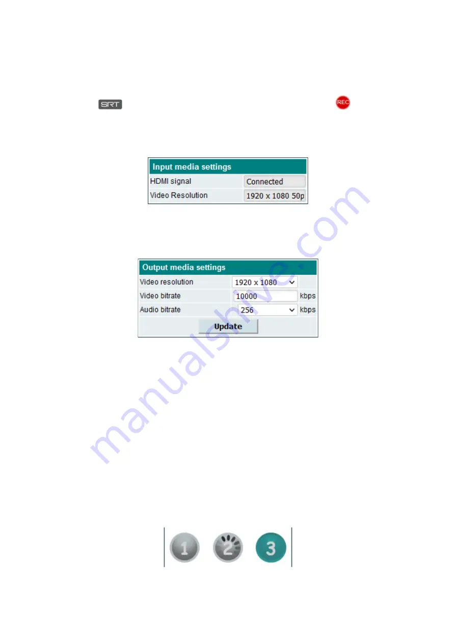
The list on the right side shows the TV channels that you are currently watching or recording. If SRT protocol
is used, mark
is displayed in the corner. Recordable channel will be marked with a
mark.
5.2 HDMI encoder
This section shows the HDMI encoder video input status and output video stream parameters.
5.2.1 Input media settings
Figure 4. Input media settings menu section.
“HDMI Signal” - shows if HDMI video signal source is connected to the device or not.
“Video resolution” – connected video signal source parameters such as video resolution and frame rate.
5.2.2 Output media settings
Figure 5. Output media settings menu section.
“Video resolution” – video IP stream output resolution. You can select from 1080P, 720P, 576P available
resolutions. You can also use the “Same as input” option if you want to leave output resolution equal to the video
input source resolution.
“Video bitrate” – higher video bitrates gives you higher video quality. However, higher network bandwidth is
required as well. If device is located far from your physical location and network bandwidth is limited, you may
use lower video bitrate value such as 1000 kbps. If you are using device on your local network and network
bandwidth is not limited, then you can use higher video bitrate value such as 10000 kbps.
“Audio bitrate” – video stream audio bitrate. Select audio bitrate preset from the dropdown list. The higher
audio bitrate, the better sound quality will be.
Click “Update” to apply the changes.
5.3 Remote control
This device is equipped with infrared blaster and virtual remote controller so you can fully control STB or other
remotely controlled equipment from the streamer WEB configuration window. Before sending commands to the
STB you have to teach the buttons of the virtual remote controller. If device button color is grey then no command
is assigned to the button. If button color is green, then virtual button is programmed and you can send button
command to the remotely controlled device. It is recommended to program most of the available virtual buttons
(such as “power on/off”, channel numbers, “volume up/down”, navigation arrows, “return” and “OK” confirm keys)
so you can have full control of the STB navigation window later.
5.3.1 Teaching the virtual remote controller buttons
Figure 6. Virtual remote controller buttons.


