5
5
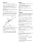
Reassembly
Check all mating surfaces. Replace any parts with scratches or
burrs that could cause leakage. Wash all metal parts in clean
solvent. Blow them dry with pressurized air. Do not wipe parts
dry with paper towels or cloth as lint in a hydraulic system will
cause damage. Check the key way and chamfered area of the
output shaft; remove any nicks, burrs, or sharp edges that could
damage the shaft seals during reassembly.
Note: Always use new seals when reassembling hydraulic
motors. Refer to parts list 6-146 for seal kit part numbers,
replacement parts, and ordering information.
Important: During reassembly lubricate the new seals with a
petroleum jelly such as Vaseline
®
. Also lubricate machined
surfaces and bearings with clean hydraulic fluid.
8 Remove all of the old Loctite
®
from the mounting flange cap
screws and their threaded holes. The threads must be clean and
dry for the new Loctite to hold properly.
9 Lubricate and install the output shaft, needle thrust bearing,
and bearing race into the housing.
Important: Do not permit oil to get into the four threaded
holes.
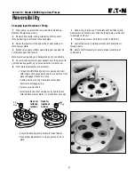
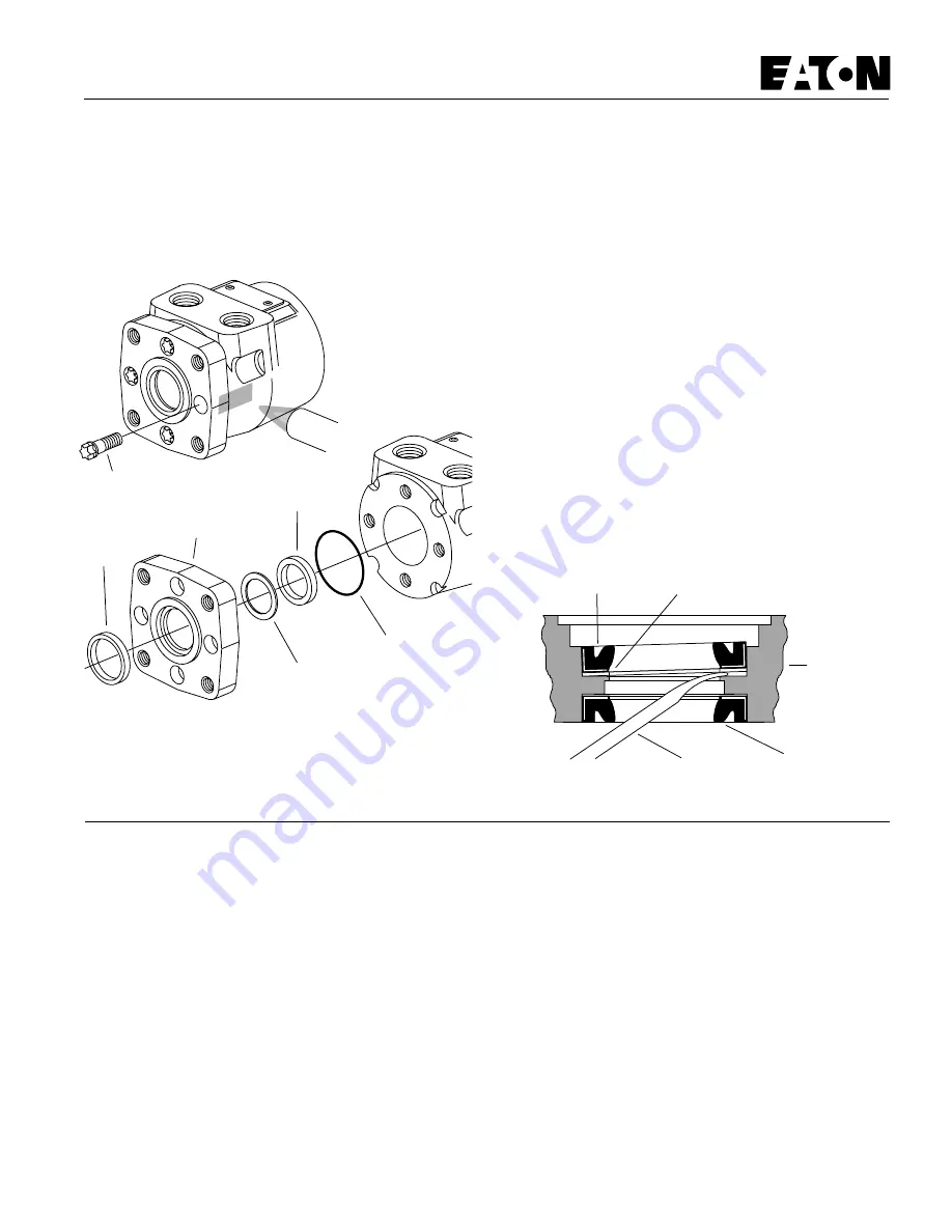
10 Lubricate the exclusion seal and press it into its seat in the
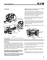
mounting flange. Figure 5 shows the correct seal orientation.
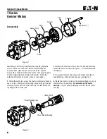
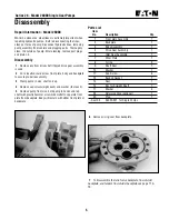
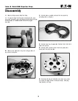
Figure 4
5 Remove the four cap screws that hold the mounting flange to
the motor housing.
Figure 3
Caution: These screws were Loctited during assembly. Do Not
exceed 56 Nm [500 lb-in] of removal torque.
If the Loctite is holding the screws too tightly, heat the motor
housing, with a propane torch, while turning the screw. Apply
heat to where the screw threads into the motor housing, see
figure 3. Apply just enough heat to remove the screw, do not
overheat the motor housing or mounting flange.
6 Remove the mounting flange from the motor housing. The
exclusion seal, pressure seal, and back-up ring will come off
with the mounting flange.
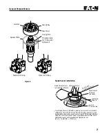
7 Carefully remove the exclusion seal, pressure seal, and back-
up ring from the mounting flange. A seal removal tool may be
fabricated by bending and rounding the end of a small blade
screwdriver, see figure 4.
Important: Do not damage the mounting flange where the shaft
passes through it.
Heat with a Propane
torch to melt Loctite
Mounting Flange
Exclusion
Seal
Back-Up Ring
Pressure Seal
Seal
Cap Screw (4)
Disassembly
Pressure Seal
Exclusion Seal
Back-Up Ring
Mounting
Flange
Seal Removal Tool
General Purpose Motors
Содержание 6200D
Страница 1: ...330395 Rev 01 6 02 Service Manual 6200D 330395 ...
Страница 4: ...GENERAL INFORMATION 1 2 6200D 330395 8 99 ...
Страница 18: ...GENERAL INFORMATION 1 16 6200D 330395 8 99 ...
Страница 20: ...CHASSIS 2 2 6200D 330395 8 99 ...
Страница 74: ...CHASSIS 2 56 6200D 330395 8 99 ...
Страница 76: ...SWEEPING 3 2 6200D 330395 8 99 ...
Страница 138: ...SWEEPING 3 64 6200D 330395 6 02 ...
Страница 140: ...ELECTRICAL 4 2 6200D 330395 8 99 ...
Страница 176: ...ELECTRICAL 6200D 330395 6 02 4 38 ELECTRICAL SCHEMATIC 353188 D ...
Страница 177: ...ELECTRICAL 4 39 6200D 330395 6 02 WIRE HARNESSES GROUP 352986 353189 D ...
Страница 178: ...ELECTRICAL 6200D 330395 6 02 4 40 WIRE HARNESSES GROUP 352986 353189 D ...
Страница 179: ...ELECTRICAL 4 41 6200D 330395 6 02 WIRE HARNESSES GROUP 352986 353189 D ...
Страница 180: ...ELECTRICAL 6200D 330395 6 02 4 42 WIRE HARNESSES GROUP 352986 353189 D ...
Страница 181: ...ELECTRICAL 4 43 6200D 330395 6 02 WIRE HARNESSES GROUP 352986 353189 D ...
Страница 182: ...ELECTRICAL 6200D 330395 6 02 4 44 WIRE HARNESSES GROUP 352986 353189 D ...
Страница 184: ...HYDRAULICS 5 2 6200D 330395 8 99 ...
Страница 212: ...HYDRAULICS 5 30 6200D 330395 8 99 HYDRAULIC SCHEMATIC PROPEL ...
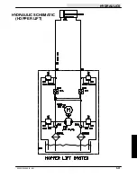
Страница 213: ...HYDRAULICS 5 31 6200D 330395 8 99 HYDRAULIC SCHEMATIC HOPPER LIFT ...
Страница 214: ...HYDRAULICS 5 32 6200D 330395 6 02 OUT IN B A B A 2 3 4 5 6 1 HYDRAULIC HOSE DIAGRAM PROPEL ...
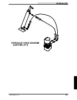
Страница 215: ...HYDRAULICS 5 33 6200D 330395 6 02 HYDRAULIC HOSE DIAGRAM HOPPER LIFT ...
Страница 219: ...No 7 145 November 1996 Char Lynn Hydraulic Motor T Series General Purpose Geroler Motor 001 Repair Information ...
Страница 220: ...2 2 General Purpose Motors ...
Страница 227: ......
Страница 228: ......
Страница 229: ......
Страница 230: ......
Страница 231: ...No 7 624 October 1995 Eaton Gear Pumps Repair Information Series 26 Model 26000 Single Gear Pumps ...
Страница 248: ...ENGINE DIESEL 6 2 6200D 330395 8 99 ...
Страница 268: ...ENGINE DIESEL 6 22 6200D 330395 8 99 ...

