background image


09419A DCN8342 

Teledyne API Model 480L O

3

 Monitor User Manual 

41 


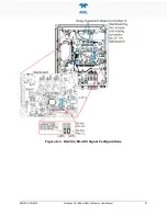
Figure 6-1. RS-232/RS-485 Signal Configurations 

Содержание 480L

Страница 1: ...e API TAPI 9970 Carroll Canyon Road San Diego CA 92131 1106 Toll Free 1 800 324 5190 Phone 1 858 657 9800 Fax 1 858 657 9816 Email api sales teledyne com Website http www teledyne api com Copyright 20...

Страница 2: ......

Страница 3: ...NOTICE OF COPYRIGHT 2021 Teledyne API Inc All rights reserved TRADEMARKS All trademarks registered trademarks brand names or product names appearing in this document are the property of their respect...

Страница 4: ...protection or proper tools could result in damage to the part s and or the instrument Technician Symbol All operations marked with this symbol are to be performed by qualified maintenance personnel on...

Страница 5: ...ignements sp cifiques MISE EN GARDE Surface chaude Ne pas toucher Toucher certaines parties de l instrument sans protection ou sans les outils appropri s pourrait entra ner des dommages aux pi ces ou...

Страница 6: ...ent provided but not manufactured by TAPI is warranted and will be repaired to the extent and according to the current terms and conditions of the respective equipment manufacturer s warranty Product...

Страница 7: ...ted to the careful and effective use of the instrument and related pertinent information ATTENTION COULD DAMAGE INSTRUMENT AND VOID WARRANTY This special notice provides information to avoid damage to...

Страница 8: ...NS 17 3 4 1 Analog Output 18 3 4 1 1 Analog Output Hardware Verification or Conversion 18 3 4 2 Status Outputs 19 3 4 3 High Current Relay Outputs 20 3 4 4 Multi Stream Signal Outputs 21 3 4 5 Failsaf...

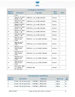
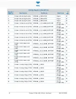
Страница 9: ...Supported 42 6 3 2 Notes on MODBUS Registers 42 6 3 3 Real Time Concentration and Status Registers Read Only 43 6 3 4 Instrument Setup and Configuration Registers Read Write 44 7 MAINTENANCE AND ADJUS...

Страница 10: ...re 7 2 J9 Pump Connector on Mainboard 49 Figure 7 3 Sensor Valve Location 50 Figure 7 4 UV LED Access 51 Figure 7 5 Sensor Module Removal 52 Figure 7 6 Display Assembly Removal 54 Figure 8 1 Display a...

Страница 11: ...software that can also be set and monitored remotely As the 480L was designed for stability reliability and simplicity it includes built in tests and diagnostics to facilitate maximum uptime Teledyne...

Страница 12: ...H Non Condensing Power 100 240 V 47 63 Hz 74 W Environmental Conditions Installation Category Overvoltage Category II Pollution Degree 2 Indoor Outdoor Use Maximum Operating Altitude 2000 meters Degre...

Страница 13: ...A per output 2 3 APPROVALS This section presents Safety and Electromagnetic Compatibility EMC compliance approvals for the Model 480L monitor 2 3 1 SAFETY IEC EN 61010 1 2010 3rd Edition Safety requir...

Страница 14: ...vapors liquids never allow contaminants to enter monitor during installation or use The combination of ozone and the catalytic ozone destruct media in the monitor can produce strong oxidation reactio...

Страница 15: ...e ventilation and for access to make adjust all connections The monitor must be mounted securely with four 4 bolts or anchors to a vertical structure or wall capable of supporting 80 lbs The mounting...

Страница 16: ...14 Teledyne API Model 480L O3 Monitor User Manual 09419A DCN8342 Figure 3 2 Mounting Hole Locations and Dimensions...

Страница 17: ...connections a 5 A circuit breaker is recommended and that it fulfills the following requirements be located as near to the instrument as possible quickly and easily accessible clearly labeled as the d...

Страница 18: ...ect voltage and frequency WARNING Verify that the instrument specification for proper line voltage and frequency is followed Observe local electrical codes when connecting power to the monitor 2 Turn...

Страница 19: ...ted internally in the instrument See Figure 3 4 for their locations Connection to these terminals is usually made via a conduit connection to the NEMA enclosure There are two conduit penetrations on t...

Страница 20: ...og output and calibration of external measurement equipment This mode is described in Section 5 2 3 1 3 4 1 1 ANALOG OUTPUT HARDWARE VERIFICATION OR CONVERSION To change or verify the configuration of...

Страница 21: ...onnector as the Analog output and which mirror the state of the values shown in the Status area of the menu structure The status outputs are defined in Table 3 1 Electrically these outputs are optical...

Страница 22: ...oads Important IMPACT ON READINGS OR DATA Contact life may be dramatically shortened if inductive loads are driven without any provision for minimizing high voltage inductive kick that can occur These...

Страница 23: ...ured using the Failsafe Operation variable found in the Setup Vars menu When the Failsafe operation has been set to ON the open collector transistors for the Status Outputs Invalid Reading Check lamp...

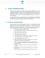
Страница 24: ...ergized 3 4 6 DIGITAL COMMUNICATION INTERFACES Note Ensure that there are no communication devices connected until after start up is complete 3 4 6 1 ETHERNET For network or Internet communication wit...

Страница 25: ...nual 23 3 5 PNEUMATIC CONNECTIONS Note Sample tubing made from an inert material such as Teflon should be used to minimize sample degradation Figure 3 6 Pneumatic Connections Single Stream Figure 3 7...

Страница 26: ...ipped with an internal particulate filter down stream of the selector manifold In addition it is recommended that inlet filters be installed at the inlet of each sample line These filters should be co...

Страница 27: ...y contain small amounts of condensed water This coalescing filter removes not only liquid but also particulates with a Teflon filter element Due to the additional volume added by the coalescing filter...

Страница 28: ...gas in a humid environment It is an alternative option when there is no risk of condensation The permeation material is a Teflon type compound and has only a minimal effect on the ozone concentration...

Страница 29: ...DCN8342 Teledyne API Model 480L O3 Monitor User Manual 27 3 6 PNEUMATIC FLOW DIAGRAM Figure 3 8 480L Pneumatic Diagram w Sample Conditioner and Permeation Gas Dryer Options single stream configuration...

Страница 30: ...ired Teledyne API also recommends that the Model 480L be re calibrated once a year Teledyne API can provide NIST traceable calibration services at our factory or on site Please contact our Technical S...

Страница 31: ...flow rate Briefly pressing any button causes the Home Screen to appear with ozone concentration flow rate and menu selections In multi stream monitors the default screen also shows a table listing th...

Страница 32: ...ts the selected input Pressing and holding any button for at least two seconds or pressing no buttons for at least 30 seconds returns the display directly to the Default Screen 5 1 3 INDICATOR LEDS Th...

Страница 33: ...O3 units set in Vars allow span gas to enter for 1 hour prior to execute Flow Cal set flow target based on external flow meter execute Alarm screen becomes Default Screen when alarm is triggered soli...

Страница 34: ...up period 5 2 3 DIAG MENU The DIAG menu contains functions that are useful for testing and configuring external equipment that may be connected to the I O panel of the instrument 5 2 3 1 ANALOG STEP...

Страница 35: ...LE IN port of the monitor Allow the instrument to stabilize on the span gas source for a minimum of 1 hour before performing the span calibration Note A Span Calibration should only be performed with...

Страница 36: ...Flow Cal cannot be performed because it would result in an out of range flow slope value for the monitor This means that either the flow sensor in the monitor is malfunctioning causing improper readi...

Страница 37: ...sable each stream for concentration display ON ON OFF ALARM MODE Controls the latching behavior of the concentration alarms When Latching is set to ON the alarm persists until Reset is pressed to clea...

Страница 38: ...gized in normal operation and de energized during fault status OFF ON OFF STREAM COUNT Specifies the number of streams available in the instrument Note that the hardware in the instrument must be also...

Страница 39: ...e display shows the current mode and a table of the streams highlighting the one whose concentration and flow readings are currently being measured In Auto Mode the duration of each measurement before...

Страница 40: ...the button below the Up or Down arrows will switch to the next stream To return to Auto mode either allow the instrument to switch after a 10 minute time out can be set on or off in the Setup Vars men...

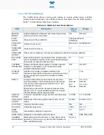
Страница 41: ...nection use the front panel control keys Section 5 1 2 to navigate to the Setup Comm Ethernet IP mode menu If you don t know what the IP Address Mask or Gateway values should be consult with your IT A...

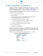
Страница 42: ...emove Relay Expansion board if installed as indicated in Figure 6 1 4 Set the desired COM as shown in Figure 6 1 where for RS 232 Normal jumper Pins 1 2 on both J20 and J23 or for RS 485 jumper Pins 3...

Страница 43: ...09419A DCN8342 Teledyne API Model 480L O3 Monitor User Manual 41 Figure 6 1 RS 232 RS 485 Signal Configurations...

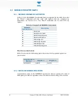
Страница 44: ...nction Code Description 01 Read Coils 02 Read Discrete Inputs 03 Read Holding Registers 04 Read Input Registers 05 Write Single Coil 06 Write Single Register 15 Write Multiple Coils 16 Write Multiple...

Страница 45: ...AM_1_O3_CONC Inverse Float Double 32 12 Stream 2 Concentration PPB STREAM_2_O3_CONC Inverse Float Double 32 14 Stream 3 Concentration PPB STREAM_3_O3_CONC Inverse Float Double 32 16 Stream 4 Concentra...

Страница 46: ...Sampling STREAM_1_ACTIVE Boolean 1 13 Stream 2 Active Status 1 Sampling STREAM_2_ACTIVE Boolean 1 14 Stream 3 Active Status 1 Sampling STREAM_3_ACTIVE Boolean 1 15 Stream 4 Active Status 1 Sampling ST...

Страница 47: ...1 HI HI Alarm Enable 1 ON STREAM_1_HI_HI_ALARM_ENABLE Boolean 1 13 Stream 2 HI HI Alarm Enable 1 ON STREAM_2_HI_HI_ALARM_ENABLE Boolean 1 14 Stream 3 HI HI Alarm Enable 1 ON STREAM_3_HI_HI_ALARM_ENABL...

Страница 48: ..._6_HI_ALARM_SETPOINT Inverse Float Double 32 24 Stream 1 HI HI Alarm Limit PPB STREAM_1_HI_HI_ALARM_SETPOINT Inverse Float Double 32 26 Stream 2 HI HI Alarm Limit PPB STREAM_2_HI_HI_ALARM_SETPOINT Inv...

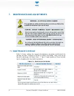
Страница 49: ...g material Generic plastic glasses are not adequate 7 1 MAINTENANCE SCHEDULE Table 7 1 below outlines the suggested maintenance procedures and intervals for ensuring the 480L continues to operate accu...

Страница 50: ...nt when power is connected to the instrument Figure 7 1 shows the internal layout of the 480L as reference in the procedures that follow Note the locations of the Power Supply and the Electrical Termi...

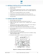
Страница 51: ...ACEMENT 1 Disconnect power from the monitor 2 Open front panel and locate sample pump assembly See Figure 7 1 3 Unplug the pump power connector from the mainboard PCA at connector J9 Figure 7 2 4 Keep...

Страница 52: ...residue or dirt off the surface of the manifold using a lint free cloth and distilled or DI water 9 Install the new valve by reversing steps 1 7 Note the proper orientation of the new valve as noted...

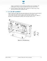
Страница 53: ...value on display for a couple minutes to verify that it does not drift out of the adjustment range 7 7 UV LED REPLACEMENT The UV LED can be replaced by disconnecting the power cable from the sensor m...

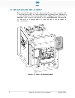
Страница 54: ...from the sensor PCA that run to J13 Bench Supply and J10 Bench Serial Interface on the Mainboard and by disconnecting the pneumatic tubing at the sample filter and at the input to the scrubber Then re...

Страница 55: ...e display cable from the securing clips 4 Carefully remove the EMI core from the enclosure and remove any remaining adhesive from the door 5 Using a Star T10 screwdriver remove the screws securing the...

Страница 56: ...tion pins for configuring either Analog output Figure 3 5 or Serial communications Figure 6 1 1 Power off the instrument 2 Locate the relay expansion board Figure 3 5 or Figure 6 1 and remove the four...

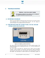
Страница 57: ...al reference if needed 8 2 TROUBLESHOOTING WITH FRONT PANEL STATUS LED AND DETAILS OR STATUS OUTPUTS Figure 8 1 Display and Control Panel The status LED on the front panel reflects the current operati...

Страница 58: ...us output state Triggers Critical Warning 1 Sensor OK Red Open No bench communications Reference 125 0 mV Measure 1230 0 mV Yes 2 Invalid Reading Yellow Closed O3 Concentration is too low Units O3 Con...

Страница 59: ...will read ERROR If the monitor is consistently reading negative values then a zero calibration should be performed see Section 5 2 3 2 If the monitor is consistently reading values in excess of the fu...

Страница 60: ...is a problem with the pressure sensor on the Sensor Module and the Sensor Module should be replaced Next reconnect the pump and disconnect all sample lines from the monitor and see if the pressure in...

Страница 61: ...ozone absorption coefficient path length 3 O C concentration of ozone in ppb T sample temperature in Kelvin P pressure in inches of mercury As can be seen the concentration of ozone depends on more t...

Страница 62: ...y aging and dirt The electronic platform is based on a Controller Area Network CAN bus modular system CAN is the central networking system that enables communication among all the parts and facilitate...

Отзывы: