22
Teledyne API Model 480L O
3
Monitor User Manual
09419A DCN8342
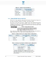
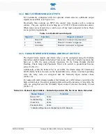
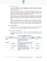
Table 3-6. Relay Functions - Failsafe Operation ON, No Alarms Triggered
Relay #
Function
Failsafe Operating State
1
System OK *
Energized
2
Hi Alarm
Energized
3
Hi-Hi Alarm
Energized
* Failsafe setting does not change System OK behavior.
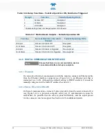
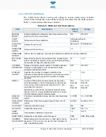
Table 3-7. Multi-Stream Outputs - Failsafe Operation ON
Function
Normal Operation- No Alarm
Present
Failsafe Operating State
Hi Alarm
Stream X Hi Alarm Off
Energized
Hi-Hi Alarm
Stream X Hi-Hi Alarm Off
Energized
Hi Alarm
Stream X Hi Alarm is triggered
De-energized
Hi-Hi Alarm
Stream X Hi-Hi Alarm is triggered De-energized
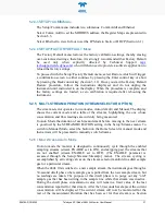
3.4.6 DIGITAL COMMUNICATION INTERFACES
Note
Ensure that there are no communication devices
connected until after start-up is complete.
3.4.6.1
E
THERNET
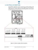
For network or Internet communication with the monitor, connect an Ethernet cable
from the Ethernet interface connector (see Figure 3-4) to an Ethernet port that is
connected to a LAN. Although the default setting is DHCP-enabled, it should be
manually configured with a Static IP address (Section 6.1).
3.4.6.2
S
ERIAL
:
RS-232
OR
RS-485
For Serial communication, connect a 9-pin serial cable from the serial connector J14
(see Figure 3-4) to a personal computer serial port. If communication cannot be
established, it’s possible that the cable is pinned differently, and the signal pinout
for the connector can be swapped. See Section 6.2 for additional details.


