40
Teledyne API Model 480L O
3
Monitor User Manual
09419A DCN8342
6.2 SERIAL CONFIGURATION - RS-232 AND RS- 485
The RS-232 or RS-485 configuration is usually used when making a one-to-one
connection between the instrument and a single computer or PLC. The
communications protocol used for serial configuration is MODBUS RTU. For
details on the MODBUS RTU specification, please see
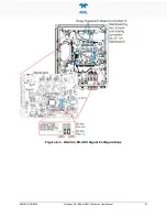
To change or verify the configuration of the serial COM, refer to Figure 3-5 while
performing the following instructions:
1.
Disconnect power from the monitor.
2.
Open front panel.
3.
Locate J20 and J23 connectors on the Mainboard PCA (remove Relay
Expansion board if installed as indicated in Figure 6-1).
4.
Set the desired COM as shown in Figure 6-1 where:
•
for RS-232 Normal, jumper Pins 1-2 on both J20 and J23, or
•
for RS-485, jumper Pins 3-4 on both J20 and J23.
5.
If applicable, reinstall/connect Relay Expansion board.
6.
Re-secure the front panel.
7.
Reconnect power to the monitor.
If there is a problem with the connection, it’s possible that the pinout signals on the
RS-232 connector need to be changed to accommodate the serial cable pins. In that
case, refer to Section 6.2 to make the adjustments for 232 XSED OVER by setting
the jumper pins 2-3 on both J20 and J23.
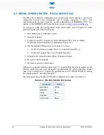
The serial port setup for RS-232/RS-485 configuration is shown in Table 6-1.
Table 6-1. RS-232/RS-485 Port Setup
Property
Value
Baud Rate
57600
Data Bits
8
Parity
None
Stop Bits
1
Flow Control
None


