32
Teledyne API Model 480L O
3
Monitor User Manual
09419A DCN8342
5.2.2 SENSOR MENU
The Sensor menu allows the operator to view various measurement parameters in
real-time. This can be useful for diagnosing various instrument or system problems.
Note that these values are updated in real-time as they are repeatedly scrolled on the
display.
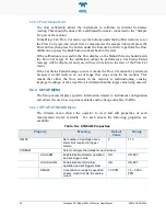
Table 5-2. Sensor Menu Parameters
Parameter
Description
Units
Normal Range*
MEAS
UV detector reading, measure cycle
mV
250 – 1230
REF
UV detector reading, reference cycle
mV
250 – 1230
CELL TEMP
Measurement of cell temperature,
depends on ambient conditions
°
C
5 - 50
O3 CELL
PRESSURE
Sample pressure
psia
9.0 – 14.9
FLOW
Sample Gas Flow Rate
cc/min
640 – 960
*After initial 5 minute warm-up period.
5.2.3 DIAG MENU
The DIAG menu contains functions that are useful for testing and configuring
external equipment that may be connected to the I/O panel of the instrument.
5.2.3.1
A
NALOG
S
TEP
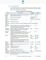
When placed in this mode, the instrument will automatically step the analog output
(see Section 3.4.1 for details on the analog output connection) through 5 points from
0 to 100 % (see Table 5-3 for values) and display the current value on the front
panel. The operator can manually control the stepping by pressing the Select button
beneath either one of the Up/Down arrows. The 5 points will correspond to the
following analog output values depending on whether the output is configured for 0-
5V or 4-20mA:
Table 5-3. Analog Step Test Values
Point
0-5V Output
4-20 mA Output
0%
0.00 V
4 mA
25%
1.25 V
8 mA
50%
2.50 V
12 mA
75%
3.75 V
16 mA
100%
5.00 V
20 mA
Press the Back button to exit from the Analog Step test function.

