30
Teledyne API Model 480L O
3
Monitor User Manual
09419A DCN8342
5.1.2 CONTROL KEYS
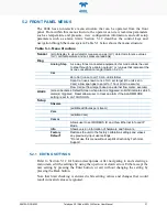
The control keys are used to view operational parameters and to view and modify
configurations of the instrument. See Section 5.2 for more detailed information.
Figure 5-2. Front Panel Selection and Control Buttons
Select: The four unmarked buttons operate the corresponding field directly
above them in the bottom of the display screen. The fields show
selectable parameters and operations for the current menu, including
left, right, up, down arrows to scroll available settings.
Back: Returns to the previous screen up, and when pressed prior to pressing
the Enter button, exits the screen without accepting selected input.
Enter: Accepts the selected input.
Pressing and holding any button for at least two seconds or pressing no buttons for
at least 30 seconds returns the display directly to the Default Screen.
5.1.3 INDICATOR LEDS
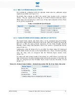
The default state of the the STATUS LED is solid lit green. When lit red
or yellow, it indicates there is an error with any one or more of four parameters:
Sensor OK (red), Invalid Reading (yellow), Check Lamp (yellow), or Pneumatic
Error (yellow). Details of the error type will be shown as the Default Screen if an
error is present or the user can view the state of these parameters in the Status
Menu.
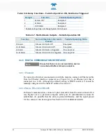
The default state of the ALARM LED is off. When lit red, an alarm has
been triggered and the display immediately switches to the Alarm screen; a
table indicates by a solid filled radio button whether there is a Hi Alarm or a Hi Hi
Alarm (and in the case of a multi-stream monitor, it also shows which stream(s)
is(are) affected).

