29
Installing the Equipment
2.5.3
Connecting the 3200 Series 1+1 System VoIP Network(s)
Each 3200 series unit and 3200 1 unit features dual GigE ports for connection to different VoIP
networks. This provides an access point to manage VoIP traffic. Should one of the IP networks fail, the
3200 series 1+1 system will continue to manage VoIP traffic using the alternate network.
The IP address of the VoIP ports can be modified using the web portal.
Note:
The 3200 series 1+1 system requires two (2) gigabit layer 2 Ethernet switches.
Prerequisites
To connect the 3200 series unit and 3200 1 unit to the VoIP network, you will need:
•
Two gigabit layer 2 Ethernet switches. A second one is required to support redundancy of the VoIP
interface.
•
Four CAT5 Ethernet cables with RJ45 male-male terminations.
•
Two IP addresses located on different subnets.
Connections
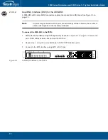
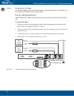
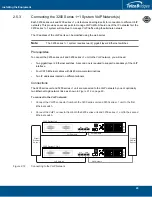
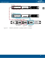
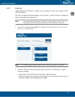
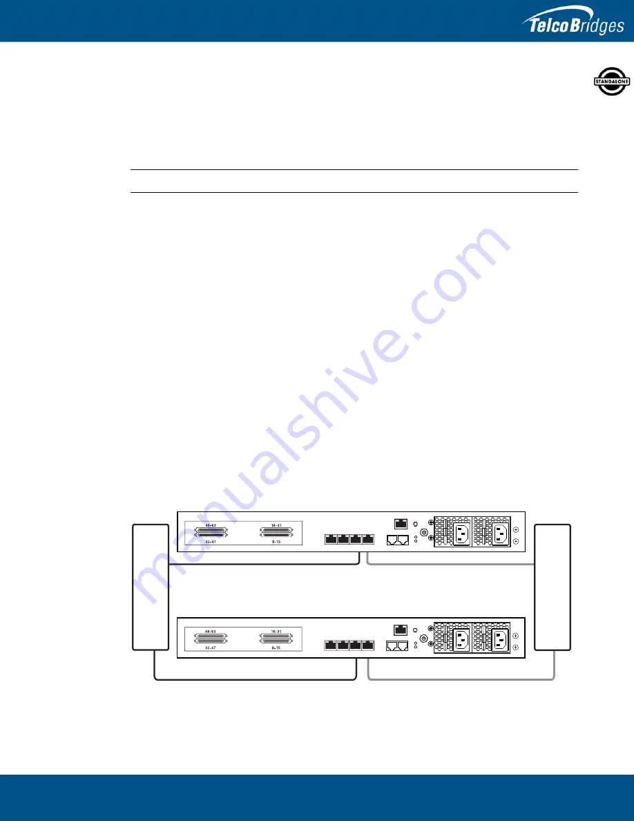
The 3200 series unit and 3200 1 unit are connected to the VoIP network by one or optionally
two Ethernet GigE network links, as shown in
To connect to the VoIP network:
1.
Connect the VoIP0 connector from both the 3200 series unit and 3200 1 unit to the first
Ethernet switch.
2.
Connect the VoIP1 connector from both the 3200 series unit and 3200 1 unit to the second
Ethernet switch.
Figure
2.12
Connecting to the VoIP Network
VoIP Network
VoIP Network
VoIP Network
VoIP Network
3200 Series Unit
3200 1 Unit
Gi
g
abit
Ethernet
Switch 1
MGMT0
ETH
VOIP
0
1
0
1
TMS
0
1
Gi
g
abit
Ethernet
Switch 2
MGMT0
ETH
VOIP
0
1
0
1
TMS
0
1

