3200 Series Standalone and 3200 Series 1+1 System Installation Guide
24
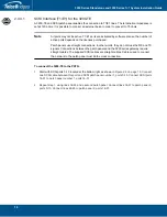
2.4.5.2
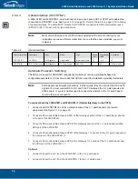
Connecting to DC Power
The 3200 series gateway DC model is furnished with two DC power connection ports. In addition, each
DC powered unit is supplied with two DC power cables.
Fuse and Cabling Requirements
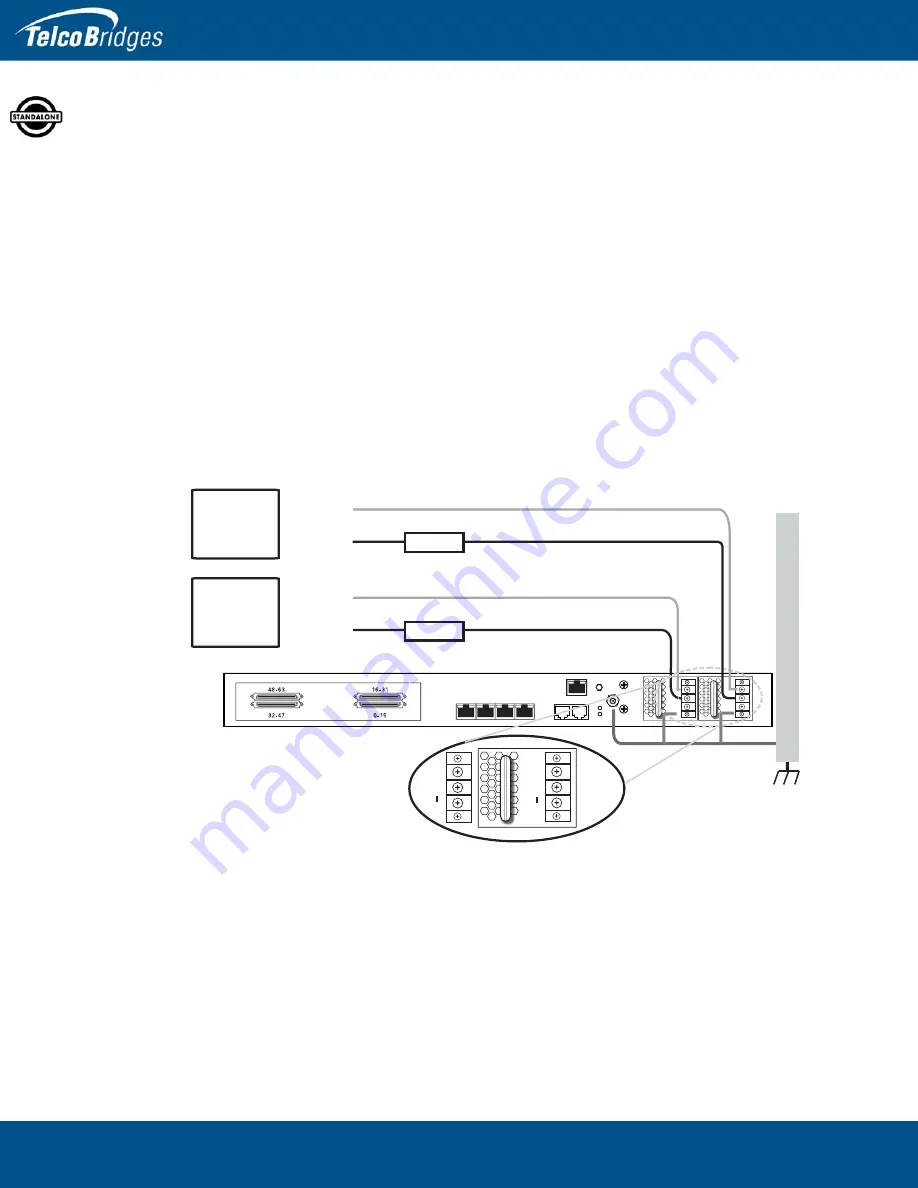
16 AWG wiring must be used and the 48V supply must be protected with a customer provided 5A 48V
fuse.
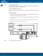
To connect o DC power:
1.
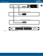
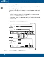
Connect one wire from the positive terminal of the 3200 series gateway to the return side of DC
power source one, as shown in
2.
Connect another wire from the negative terminal of the 3200 series gateway to the -48V side of DC
power source one.
3.
Connect a ground wire from the ground terminal of the 3200 series gateway to earth ground.
4.
Repeat steps 1-3 for the second power DC power source.
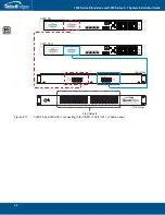
Figure
2.9
3200 Series Gateway DC Wiring Diagram
MGMT0
ETH
VOIP
0
1
0
1
TMS
0
1
D
C
Power
So
u
rce 1
Ret
u
rn
-
4
8V
5
A f
u
se
Ret
u
rn
-
4
8V
D
C
Power
So
u
rce 2
+
-
---
+
-
---
Earth Gro
u
nd
Gro
u
nd Bar
5
A f
u
se

