4-60
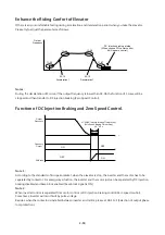
Enhance the Riding Confort of Elevator
If there is any uncomfortable feeling during acceleration and deceleration period when you take the elevator.
Please try to adjust the parameters as follows.
11-04
11-05
11-06
11-07
Output
Frequency
DC injection braking at stop
(When you use PG vector control,
it will be zero control)
00-14
Acceleration1
00-15
Deceleration1
Notes:
During the deceleration of S curve, if the output frequency is lower than 01-08, the function of S curve will be
stopped and then transfer to DC injection braking (Zero Speed Control).
Function of DC Injection Braking and Zero Speed Control.
ON
Output
Frequency
OFF
OFF
ON
Frequency
Output
DC Brake
07-08(DC Injection Braking Time at Stop)
(Zero Speed Braking Time at Stop)
0.3 ~0.5 s
Note 1:
According to the standards of European market, when the elevator is stop, the inverter and the motor has to be
separated by contactor. For emergency situation, the inverter and the motor just can be separated by DC injection
braking disabled and base block enabled (base block signal is ON)
Note 2:
When inverter control is separated from motor control or DC injection braking control (Zero speed control).
Sometimes, inverter will occur fault by pulse voltage.
Besides, when the contactor is installed between inverter and motor, please et 08-10=1 (Selection of output phase
loss protection).
Содержание E510-201-SH
Страница 1: ......
Страница 20: ...3 6 NEMA1 Step1 Remove the terminal cover Step2 Wire Re install the cover Step3 Put the terminal cover back ...
Страница 27: ...3 13 3 2 3 External View 3 2 3 1 IP20 NEMA 1 a 200V 0 5HP 1HP 400V 1HP 2HP 200V 2HP 3PH IP20 NEMA1 ...
Страница 28: ...3 14 b 200V 2HP 1 3PH 200V 3HP 20HP 400V 3HP 25HP IP20 NEMA1 ...
Страница 29: ...3 15 c 200V 25HP 400V 30HP d 200V 30HP 40HP 400V 40HP 75HP ...
Страница 47: ...3 33 Frame2 Three phase 200V 3HP Frane 5 6 Three 200V 25HP Frame 5 6 Three phase 200V 30HP 40HP ...
Страница 49: ...3 35 Frame 5 Three phase 400V 30HP Frame 6 Three phase 400V 40HP 50HP Frame 6 Three phase 400V 60HP 75HP ...
Страница 51: ...3 37 3 5 Standard Wiring 10V AI1 AI2 AGND E P P ...
Страница 72: ...4 6 4 1 4 Example of keypad operation Example 1 Modifying parameters ...
Страница 74: ...4 8 4 1 5 Operation control ...
Страница 206: ...4 140 Acceleration Deceleration calculation of mode 2 ...
Страница 310: ...4 244 P mode output i1 PQ1 I1 OFF ON OFF ON OFF ON OFF i1 is the inverse logic of I1 i1 Q1 ON OFF ON OFF ...
Страница 316: ...4 250 6 Timer mode 6 FLASH Timer mode 2 7 Timer mode 7 FLASH Timer mode 3 ...
Страница 424: ...REVISIONS Date Manual Number Revision May 2017 4KA72X645T01 First edition ...
Страница 425: ......


