


User Manual
7
Chapter 4: DVR Boot up
4.1 System Initialization
Picture 4-1
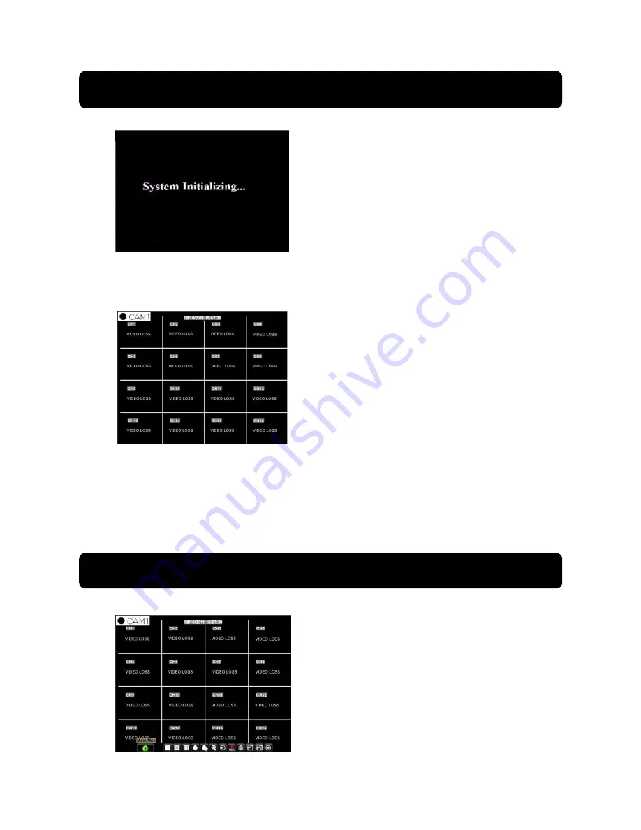
4.2 Live Interface
Picture 4-2
area outside the menu allows you exit the Pop-up menu.
Note:
When internal HDD is not connected or an error occurs, the character “H” will
appear on the first channel of the live screen and accompany buzzer alarm. If you want to
close the buzzer alarm, please enter into [Main menu
Alarm] to set HDD loss, HDD
space not enough and alarm output to “off”
Chapter 5: DVR Menu
5.1 Pop-up Menu
After finishing system initialization, click right
key of mouse on main interface mode to enter into
Pop-up Menu. Now you could perform parameter
setting and operate on Main Menu, Multi-Pics, PTZ,
PIP, Rec. Search, Mute, Manual record, Start
Rolling, Start Cruise and Vo Switch etc.
Clicking [0] key on the remote controller or
holding press [Esc] key on the front panel could
switch system to other output device.
After finishing initialization the system will enter into
<Live> screen. Picture 4-2 is the 16-split display
defaulted by system, which is showing no video input
status. Once there are video inputs, the screen will
display live images from the cameras. In Live mode, if
you use the mouse to double-click the live image of any
channel, the image will be maximized to full screen, by
double-clicking again, image will be come back to 16-split
display mode; clicking the right button of the mouse will
enter into Pop-up Menu; clicking the left button of the
mouse allows you select menu items; and clicking any
After connecting the Power cable of DVR to
wall outlet and pressing the Power button on the
front panel, you will enter into the system
initializing screen shown as Picture 4-1
Picture 5-1


