


CAN BUS network
108
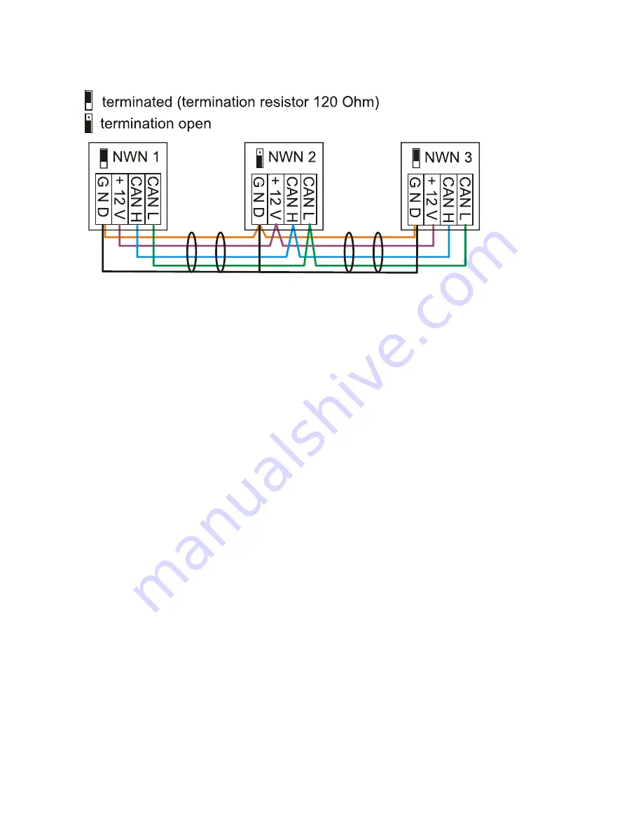
Example
: Connection of three network nodes (NK) with a 2x2-pole cable and
termination
of the
terminal network nodes (network inside one building)
Each CAN network is to be provided with a 120 ohm BUS terminator at the first and last network
subscriber (=
termination
). This is achieved with a plug-in jumper
at the back of the controller
.
Each CAN network therefore always has two terminators (one at each end). Branch cables or a star
topology are not permissible for CAN wiring.
As you can see from the tables, reliable transmission depends on a number of factors (cable type,
cross-section, length, number of nodes, etc.). All of this information can be considered relatively
conservative so that no problem should occur if you are prudent when dimensioning.
Practical help
As can be seen from the tables, reliable transmission depends on a number of factors (cable type,
cross-section, length, number of nodes, etc.).
Trials at the factory
have shown the following:
1) Branches with a star topology of up to 10 m will not impede transmission.
2) Up to a BUS length of 150 m and with only a few nodes, the cable
CAT 5 24AWG
(or higher cate-
gory; typical Ethernet cable in PC networks) can be used. This can therefore be used in many appli-
cations.
However, such networks do not comply with the recommended specification and should be tested
before the network is created with cables 50 % longer to be on the safe side.
Data link (DL bus)
Any cable with a cross section of 0.75 mm² can be used for the
data link
having a max. length of 30
m. For longer cables, we recommend the use of shielded cable. Cable channels for power and data
lines may cause a disturbance in the data lines if they lie too close to each other over long stretches.
Therefore a minimum distance of 20 cm between the two cable ducts or the use of shielded cabling is
recommended. Where the processing of two control inputs by the data converter are concerned sepa-
rate screened cables must be used. If screened cables are used, the screen must be connected to
the GND. Equally the DL must never be put through the same cable with the CAN.
The data line is connected to clamp DL (A14) and sensor earth.


