2-4
2. MAIN UNIT REPLACEMENT
EO18-33014
4)
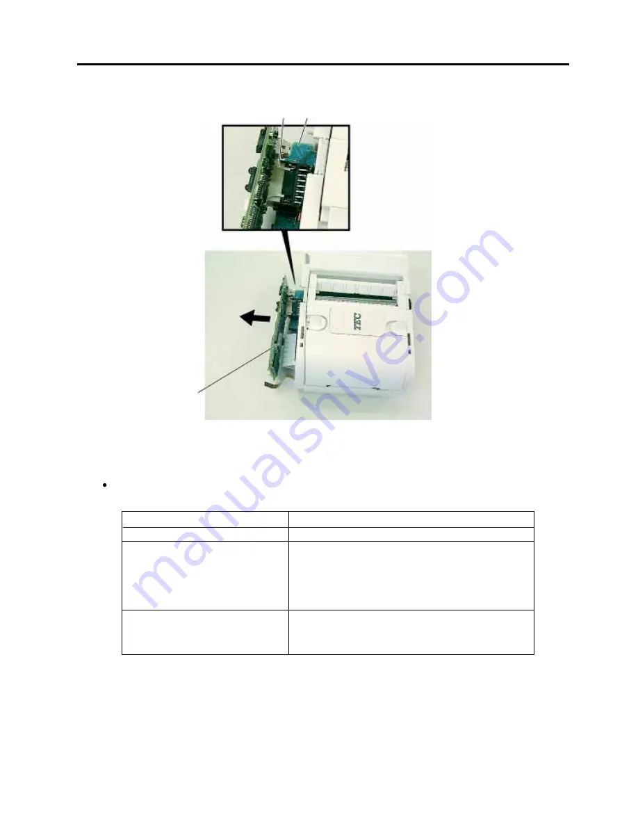
While raising the CPU PC board a little, remove the Drive PC board from CN2 on the CPU PC board.
5)
After replacing the CPU PC board with the new one, reassemble in the reverse order of removal.
After the replacement, perform each check and setting below.
(1) Status Indicator
CPU PC Board
Drive PC Board
CN2
Status Indicator
The status indicator is off.
The status indicator blinks in red for a few seconds,
then lights in green.
If the battery is nearly end, the status indicator lights
in orange. If the battery voltage is low, the status
indicator lights in red.
The status indicator blinks in red.
Condition
The printer is off.
The printer is turned on.
After the printer is turned on, the
[FEED] button is pressed without
media loaded.
When the status indicator doesn't perform as the table above shows, make sure that the cables are connected
to the CPU PC board properly. If the status indicator still doesn't perform properly, replace the CPU PC board
with the new one.
(2) Test Print
Perform a test print to check each item. (Refer to Section 2.6 TEST PRINT.)
(3) Initial Setting
With Set Up Tool, be sure to perform each sensor adjustment, destination setting, printer ID setting, and online
check printing. (Refer to Section 2.7 SETTING AND ADJUSTMENT.)
(Revision Date: Jan. 29, 2004)
2.1 REPLACING THE CPU PC BOARD AND THE WIRELESS LAN MODULE


