background image

2-1

2. MAIN UNIT REPLACEMENT

EO18-33014

WARNING!

1.

Unload the battery before replacing any parts.

2.

Danger of explosion if battery is incorrectly replaced.  Replace the battery only with 'TOSHIBA TEC
Corporation, Battery Pack Type B-SP2D-BT, 7.4V 1400mAh Lithium-Ion.  Discard used batteries
according to the manufacture's instructions.

All machines are generally delivered in their best condition.  Efforts should be made to keep them that way.  Lack
of oil, or the presence of debris or dust, may cause an unexpected failure.  To maintain in optimal operating
condition, periodically clean the machine and apply the proper kinds of oil to each part in which lubrication is
needed.
Although the frequency of lubrication varies according to how often the machine is used, as a minimum it is
necessary to lubricate before any part becomes dry.  It is also necessary to wipe off excessive oil or it will collect
dirt.

NOTE: Replacement procedures are partly different depending on the models.

2.1 REPLACING THE CPU PC BOARD AND THE WIRELESS LAN MODULE

For GH20/GH30 models

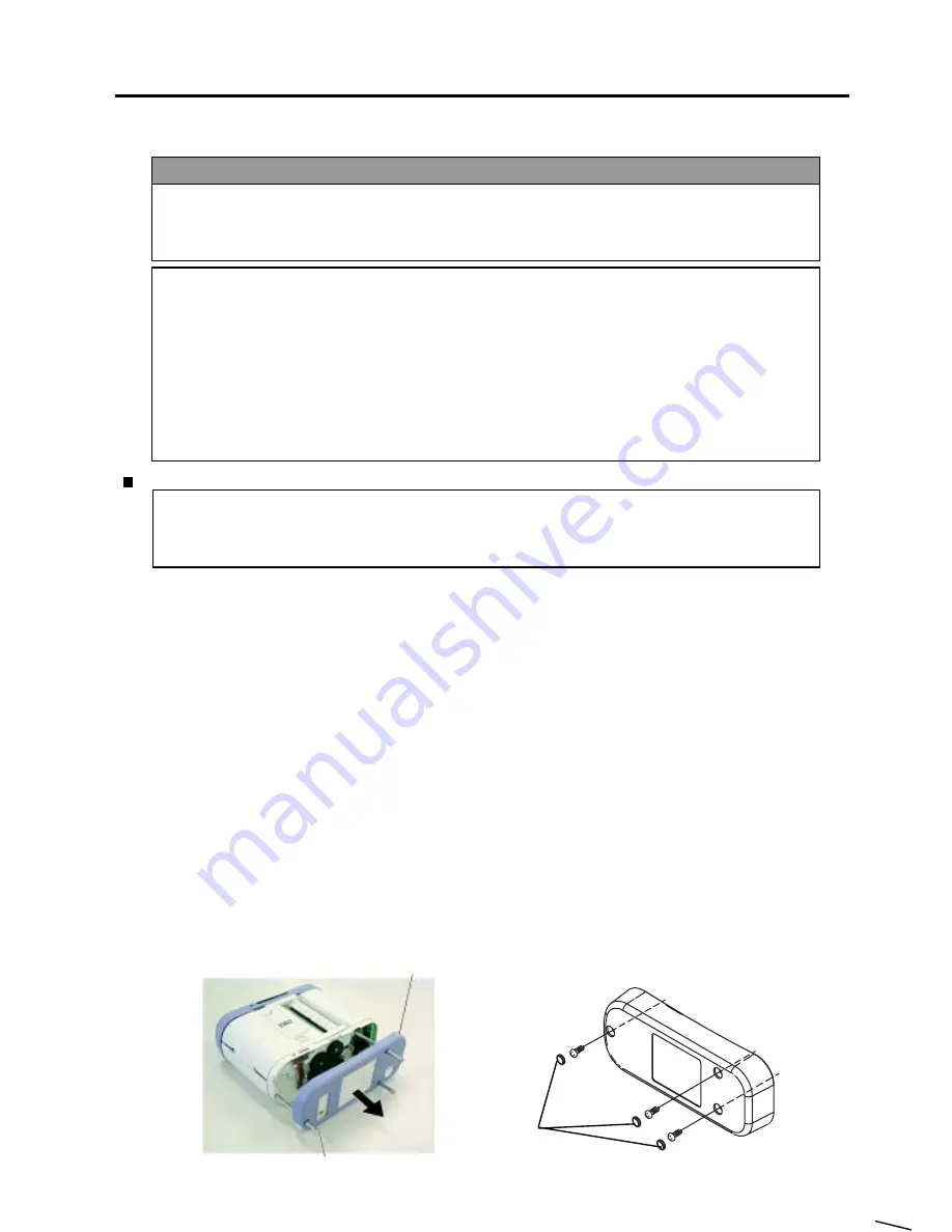
1) Remove the three cover securing screws to remove the bottom cover.  For the RoHS compliant

printers, the cover securing screws are covered with rubber caps.  First, remove the rubber caps
using tweezers or something, and then, remove the cover securing screws.  At this time, care must
be taken not to damage the bottom cover.
The removed rubber caps are non-reusable.  Please use new rubber caps (Part No.: 7FM02372000)
when reassembling the printer.

NOTES: 1. When removing the bottom cover, support the gears so that they don't come out.

2. When reassembling, tighten the cover securing screws with 2.5 to 2.8kgf

cm (0.245 to

0.275N

m).

3. When reassembling, attach the bottom cover so as not to catch the FPC cable.

(Revision Date: Mar. 10, 2006)

2.1  REPLACING THE CPU PC BOARD AND THE WIRELESS LAN MODULE


Lubrication

CAUTION!
1.

Since a lot of small molded parts are used in this printer, care must be taken not to damage or lose
them.

2.

Be careful not to damage the print head while removing and reassembling.

3.

In the United States, used lithium ion batteries should be returned to the store where you bought the
machine.  (USA only)

4.

LITHIUM ION BATTERY
DISPOSE OF PROPERLY
Caution: Do not handle damaged or leaking lithium ion battery.

5.

Before handling the main parts, be sure to discharge static electricity in human body through other
metals.  Failure to do this may damage the CPU PC board, print head, etc..

2. MAIN UNIT REPLACEMENT

CAUTION!
1.

Lubrication: During parts replacement

2.

Kinds of oil: FLOIL G-488:  1Kg can.  (Part No.19454906001)

3.

Do not spray the inside of the printer with lubricants.  Unsuitable oil can damage the mechanism.

Cover Securing Screw

Bottom Cover

Rubber Cap

Содержание B-SP2D Series

Страница 1: ...TEC Protable Printer B SP2D SERIES Original Mar 2003 Revised PRINTED IN JAPAN Maintenance Manual Document No EO18 33014 ...

Страница 2: ...arranty WARNING Follow all manual instructions Failure to do so could create safety hazards such as fire or electrocution CAUTION The country setting for the Wireless LAN Module may need to be changed according to each country s Radio Law Before selling the printers refer to Section 7 and change the setting if necessary Revision Date Feb 17 2004 ...

Страница 3: ... 2 COMMUNICATION PARAMETERS SETTING 4 3 4 3 DOWNLOAD TO THE PRINTER 4 4 4 4 DOWNLOAD TO THE WIRELESS LAN MODULE 4 10 5 TROUBLESHOOTING 5 1 6 OPTIONAL EQUIPMENT 6 1 6 1 HOW TO USE THE BATTERY CHARGER B SP2D CHG QM 6 1 6 2 HOW TO USE THE BATTERY CHARGER B SP2D CHG5 QM 6 2 7 WIRELESS LAN PARAMETER SETTING 7 1 7 1 WHEN USING THE RFLAN CONFIGURATION TOOL 7 1 7 2 WHEN USING THE WEB BROWSER 7 10 Copyrigh...

Страница 4: ...n approved one which meets the standard for each country from your Authorized TOSHIBA TEC representative For details please refer to the B SP2D CHG Owner s Manual 1 2 CHECKS 1 Check for damage or scratches on the machine 2 Confirm that none of the accessories are missing SMW 3x8 Screw Cord Clamp MediaGuide Belt Holder Battery Outer Winded Guide Owner sManual Carton Carton BatteryCharger B SP2D CHG...

Страница 5: ...ers or something and then remove the cover securing screws At this time care must be taken not to damage the bottom cover The removed rubber caps are non reusable Please use new rubber caps Part No 7FM02372000 when reassembling the printer NOTES 1 When removing the bottom cover support the gears so that they don t come out 2 When reassembling tighten the cover securing screws with 2 5 to 2 8kgf cm...

Страница 6: ...not come off 2 When reassembling tighten the PT 3x8 screws with 6kgf cm 58 8N cm 3 When reassembling be careful not to pinch the FPC cable by the bottom cover or gear cover Also connect the FPC cable to the wireless LAN module with the terminal side facing to the bottom cover Then lock the FPC cable with the connector lock Gear Cover Wireless LAN Module Bottom Cover PT 3x8 Screw FPC Cable Wireless...

Страница 7: ... the pritner NOTES 1 When removing each FPC cable unlock the connector with tweezers etc At this time be careful not to scratch the FPC cable and the CPU PC board 2 Do not fold back the FPC cables Doing so may damage the internal wires Battery Cover Top Cover CPU PC Board CN101 Print Head FPC CN102 Sensor 1 FPC CN103 Interface FPC CN104 Sensor 2 FPC Revision Date Jan 29 2004 2 1 REPLACING THE CPU ...

Страница 8: ...ator lights in red The status indicator blinks in red Condition The printer is off The printer is turned on After the printer is turned on the FEED button is pressed without media loaded When the status indicator doesn t perform as the table above shows make sure that the cables are connected to the CPU PC board properly If the status indicator still doesn t perform properly replace the CPU PC boa...

Страница 9: ...RS 232C 3 Release the connector lock to disconnect the FPC cable and then pull out the interface PC board Bluetooth or RS 232C 4 Remove the gears from the printer in the following order 1 motor idler gear 2 idler gear 3 platen idler gear 5 Remove the 1 stepping motor ass y 2 ATC battery terminal ass y and 3 drive PC board from the printer as an assembly 6 Remove the stepping motor ass y and the AT...

Страница 10: ...C board and the stepping motor ass y with the new ones reassemble in the reverse order of removal NOTES 1 When reassembling the stepping motor ass y fit the positioning pins into the mounting hole of the motor bracket as the figure below shows 2 For the GH20 model when attaching the motor braket to the printer make sure that the earth spring on the motor braket comes in contact with the printer s ...

Страница 11: ... gear and the motor idler gear 4 After reassembling the gears manually rotate the gears to make sure that they works properly 5 Make sure of the orientation of the gears and then reassemble them in the following order 1 platen idler gear 2 motor idler gear 3 idler gear 3 Idler Gear 1 Platen Idler Gear 2 Motor Idler Gear Revision Date Jun 13 2003 2 2 REPLACING THE DRIVE PC BOARD AND THE STEPPING MO...

Страница 12: ... LAN module and gear cover Refer to Section 2 1 REPLACING THE CPU PC BOARD AND WIRELESS LAN MODULE 2 Remove the platen gear from the platen 3 Remove the platen holders in the direction indicated by the arrows to remove the platen ass y Strip Shaft Platen Holder Platen Shaft Holder Platen 4 Remove the platen shaft holders and the platen holders from the platen and the strip shaft Platen Ass y Plate...

Страница 13: ...with the new one reassemble in the reverse order of removal NOTES 1 Before reassembling the platen gear wipe away dusts stain or dirt on the gear with a clean cloth 2 Make sure of the orientation of the platen gear then reassemble is as the picture below shows Platen Gear Outer Side Inner Side ...

Страница 14: ...electricity in human body through other metals Failure to do this may damage the print head element 2 Never touch the print head element directly by hands or hard objects Doing so will damage the element causing a dot missing and a print failure 1 Open the media cover 2 Release the four hooks to remove the print head cover ass y Hook Print Head Cover Ass y 3 Pull out the print head shaft Print Hea...

Страница 15: ...g careful not to touch the print head element FPC Harness 5 Remove the SMW 2 6x6 screw to remove the print haed from the print head plate Head Connector Print Head SMW 2 6x6 Screw Print Head Plate SMW 2 6x6 Screw 6 Release the two hooks which are provided at the inside of the media cover and then remove the blind plate Media Cover Hook Blind Plate ...

Страница 16: ...rew 8 When replacing the print head FPC sensor 1 FPC or sensor 2 FPC follow Step 9 and after 9 Remove the bottom cover top cover CPU PC board drive PC board stepping motor ass y and gears For the GH40 model also remove the wireless LAN module and gear cover Refer to Sections 2 1 REPLACING THE CPU PC BOARD AND WIRELESS LAN MODULE 2 2 RE PLACING THE DRIVE PC BOARD AND THE STEPPING MOTOR ASS Y and 2 ...

Страница 17: ...er and the media guide 2 4 REPLACING THE PRINT HEAD CUTTER AND SENSORS Media Cover Media Guide Media Cover Shaft 11 Remove the FPC of the sens 1 PC board ass y from the frame After performing Step 10 and Step 11 Frame Sens 1 PC Board Ass y Media Cover Media Guide Media Cover Shaft Frame Print Head Cover ...

Страница 18: ...S 12 Remove the rivet and then remove the sens 1 PC board ass y from the print head cover 13 Remove the print head FFC harness from the frame Print Head FFC Harness Frame Sens 1 PC Board Ass y Rivet 14 Remove the dust sheet from the upper media cover switch Dust Sheet Media Cover Switch ...

Страница 19: ...Board Strip Batch Sensor Black Mark Feed Gap Sensor Media Cover Switch 15 Remove the upper media cover switch strip batch sensor and black mark feed gap sensor which are provided for the sens 2 PC board from the frame 16 Remove the dust sheet from the lower media cover switch Dust Sheet Media Cover Switch ...

Страница 20: ...lower media cover switch which are provided for the sens 2 PC board from the frame 18 Remove the lower media cover switch with the sens 2 PC board from the frame 19 After replacing the print head cutter and sensors with the new one reassemble in the reverse order of removal NOTES 1 Reassemble the cover springs properly when attaching the media cover shaft Sens 2 PC Board Frame ...

Страница 21: ...nter works properly as the table below shows 2 4 REPLACING THE PRINT HEAD CUTTER AND SENSORS Condition Media cover release catches are fully released Either of the media cover release catch is released Media cover release catches are locked Performance The printer doesn t feed the paper The status indicator flashes in red The printer feeds the paper 4 When the printer doesn t work properly the med...

Страница 22: ...e the strip cover to the direction indecated by the arrow 3 Remove the two strip support guides in the direction indicated by the arrows 4 Remove the strip roller together with the strip roller holders from the strip cover 5 Remove the strip roller holders from the strip roller Strip Cover Strip Support Guide Strip Roller Holder Strip Roller Strip Cover ...

Страница 23: ...der of removal NOTES 1 When reassembling fit the strip roller holders to the strip roller so that their wider sides contact the strip roller springs 2 5 REPLACING THE STRIP ROLLER 2 When reassembling attach the strip support guides correctly as the picture below shows Strip Roller Holder Strip Roller Strip Support Guide ...

Страница 24: ...89012345678901 1234567890123456789012345678901 1234567890123456789012345678901 1234567890123456789012345678901 1234567890123456789012345678901 1234567890123456789012345678901 1234567890123456789012345678901 1234567890123456789012345678901 1234567890123456789012345678901 1234567890123456789012345678901 1234567890123456789012345678901 1234567890123456789012345678901 1234567890123456789012345678901 1...

Страница 25: ...efer to Section 2 7 SETTING AND ADJUSTMENT R 3 5V or more T 1 5V or more P 3 5V or more H t 5 t 20 C t Environmental temperature A t 5 t 5 C 8 Threshold PEEL 3 2V Threshold voltage of strip sensor 9 Destination code TYPE QM Destination code 10 Printer ID No ID 01234 Printer ID No 11 Print head element check HEAD OK 2 Check result of the print head broken element OK Normal NG Broken element Print h...

Страница 26: ...of the form No 3 top and No 13 bottom Versions of the form No 2 top and No 12 bottom Versions of the form No 1 top and No 11 bottom 16 Print mode MODE LABEL Print mode LABEL RECEIPT RECEIPT1 TPCL LE 17 Printer parameter PARA PC850 0 Character code Without zero slash 14 Auto power off P W 120min Auto power off 1min 5min 30min 120min 13 Print tone Print start position ADJ 00 0 0mm Print position fin...

Страница 27: ...ly EVEN NON Baud rate RS 232C only 9 600 19 200 38 400 115 200 BD address Bluetooth only or MAC address Wireless LAN only Revision Date Jan 29 2004 2 6 TEST PRINT 18 Loopback test LOOP IR OK BT OK NOTE The check result of RS 232C interface will be NG because a special jig is used Check result of IrDA OK NG Check result of the option device interface RS RS 232C BT Bluetooth LN Wireless LAN OK NG RS...

Страница 28: ... sensor replacement or a sensor adjustment was performed in this case the CPU PC board is not replaced 1 Perform a test print Refer to Section 2 6 TEST PRINT Make sure that the paper type is set to LABEL mode Refer to Section 2 7 1 Selecting Paper Type 2 Install the Set Up Tool on a PC Refer to Section 2 7 2 Set Up Tool 3 Register a destination Refer to Section 2 7 4 Registering Destination Select...

Страница 29: ...2 25 2 MAIN UNIT REPLACEMENT EO18 33014 2 7 1 Selecting Paper Type Type of paper to be issued can be selected on the printer Select LABEL mode by following procedures below 2 7 SETTING AND ADJUSTMENT ...

Страница 30: ... trademarks of Microsoft Corpora tion Installed memory of 16MB minimum 32MB or more is recommended Available hard disk space of 10MB minimum 10MB or more is recommended Interface For IrDA communication the IrDA interface should be provided for the PC without drivers such as IrLAP or an IrDA device which is connectable to a serial port should be provided for the PC For RS 232C communication more th...

Страница 31: ...s has already been registered set F1 Transmission Control and F2 Destina tion to IrDA IrCOMM and Japan respectively and register them Then adjust the sensors When using the keyboard press the F1 or F2 key together with the Ctrl key To increase efficiency until when the printer is turned OFF from when reading the sensor A D values and each sensor adjustment are performed a feed is not performed whe...

Страница 32: ...flective sensor 3 Adjusting transmissive strip sensors Remove labels from the backing paper of the specified paper then place only the backing paper on the transmissive sensor Pass the backing paper through the path for the strip issues Press the F5 key of the keyboard or click on the F5 Transmissive Strip sensor button on the screen The transmissive and strip sensors will be adjusted When the adj...

Страница 33: ...ill blink in green for several seconds then printer prints the self test result To register the destination face the IrDA jig Actisys IR to the upper IrDA window of the printer in this state then press the F10 key of the keyboard or click on the F10 Registration button on the screen The destination will be registered When the destination registration is normally completed the message The destinati...

Страница 34: ...her with the Ctrl key 2 7 5 Registering Printer ID Move the cursor to the printer ID entry box by pressing the F7 key of the printer Manually input the lower 6 digits of the printer s serial number in the F7 Printer ID entry box Or click on the Scanner button on the screen and scan the printer ID with a scanner Turn the printer ON face the IrDA jig Actisys IR to the front IrDA window of the printe...

Страница 35: ... Transmission Control 1 Load the paper on the path for the batch issues then press the Shift F11 keys of the keyboard Or check the Batch mode check box and click on the F11 Print button on the screen This operation results that the three labels are issued in the order of slant line print tone fine adjustment value 10 test print print tone fine adjustment value 10 and test print print tone fine adj...

Страница 36: ...of the label to the left edge of the printed rectangle 4 5 1 mm Judgment criteria of 2 Vertical scanning direction Distance from the top edge of the label to the top edge of the printed rectangle 8 0 1 mm 4 Self Test Result Printing B SP2D GH20 QM B SP2D GH30 QM Revision Date Jan 29 2004 2 7 SETTING AND ADJUSTMENT 1 2 Print tone 00 or 10 Batch 111 11 Strip 999 99 B SP2D GH40 QM ...

Страница 37: ... Loop back check LOOP on the printouts for each interface must be OK The optional device OP on the printouts must match the model NOTE The special jig is required for the loop back check for B SP2D GH20 RS If it is not used the check will result in NG For B SP2D GH30 the Bluetooth device address must be printed for the optional device OP on the printouts 2 7 SETTING AND ADJUSTMENT ...

Страница 38: ...3 1 3 ELECTRONICS EO18 33014 Revision Date Jan 29 2004 3 1 BLOCK DIAGRAM 3 ELECTRONICS 3 1 BLOCK DIAGRAM ...

Страница 39: ... a 8MB SDRAM which is used to draw print data 4 D A Converter and Sensor Sensitivity Adjust Circuit The status signals from the feed gap black mark sensor strip batch sensor ambiment thermistor print head voltage print head broken element voltage and print head temperature are sent to the A D converter of the CPU The CPU acknowledges the printer status from these signals and processes the followin...

Страница 40: ...ing motor driver generator IC etc controls the stepping motor and generates the voltages from the battery supply voltage 1 Stepping Motor Driver This circuit controls the stepping motor connected to Connector 2 Using the PM1 and PM2 signals output from the CPU PC board it generates the PMA1 PMA2 PMB1 and PMB2 stepping motor drive signals Also the PMEN signal output from the PLD on the CPU PC board...

Страница 41: ...8 Windows 2000 and Windows XP are registered trademarks of Microsoft Corporation Installed memory of 16MB minimum 32MB or more is recommended Available hard disk space of 10MB minimum 10MB or more is recommended Interface For IrDA communication the IrDA interface should be provided for the PC without drivers such as IrLAP or an IrDA device which is connectable to a serial port should be provided f...

Страница 42: ...ed to the printer Example 4 1 4 Running the Download Program for B SP2D 1 Click on the START button to access the program menu 2 Highlight Programs then highlight TOSHIBA TEC B SP2D Download And then click on Download Program for B SP2D in the screen display below 3 The screen will change to display the initial screen of the Download Program as shown below 4 After the download was completed succes...

Страница 43: ...p COM1 None RS 232C and 9600bps are programmed as default setting 2 To perform Forced Download make a check in the check box Forced download mode 3 From the firmware version V1 1 IrCOMM protocol has been supported When downloading the firmware by using the IrCOMM protocol be sure to turn the printer to the system mode as this is the only mode that enables downloading with the IrCOMM protocol In ca...

Страница 44: ...on protocol setting 9600 19200 38400 115200 bps 3 RS 232C Interface Protocol Device Name Service Name Class name Minimum Turn Around Time Link Release Threshold Time IrCOMM 9 wire B SP2D IrDA IrCOMM 1 msec 12 sec Item Baud Rate Stop Bit Data Length Parity Specification 1 bit 8 bit Forced Download 115200 bps None Normal Mode Label mode Receipt mode TPCL LE mode System mode Depending on the communic...

Страница 45: ...inks in green Blinks in green and orange alternately Blinks in green Lights in green Blinks in red IrDA TEC Protocol interfae IrDA IrCOMM interface RS 232C interface Printer to printer Source printer Destination printer NOTES 1 When downloading is completed properly the printer will be automatically reset and started 2 If an error occurs during a download the printer will stop To recover from the ...

Страница 46: ...while pressing and holding the FEED button When the the status indicator blinks slowly in red twice the printer enters the forced download mode NOTE If the status indicator doesn t blink slowly in red twice the printer doesn t enter the forced down load mode Retry to turn on the printer while pressing and holding the FEED button 2 When the printer is in the forced download mode open a file for dow...

Страница 47: ... the printer and face the IrDA interface windows of both PC or a device and the printer Direction of the printer s IrDA depends on the setting For RS 232C communication connect the printer to the PC with the RS 232C cable and then turn on the printer When the the status indicator blinks slowly in red twice the printer enters the download mode NOTE If the status indicator doesn t blink slowly in re...

Страница 48: ...1 4 3 6 Copying the Firmware from the Printer to Another Printer Without using the PC you can copy the firmware from the printer to another printer By following procedures below the firmware can be copied via IrDA communication at a high speed of 115 2K bps 1 Make sure that the two printers are off and then place them within 10 cm facing the IrDA interface win dows IrDA Communication 2 Open the so...

Страница 49: ...printers nor interrupt their IrDA interface windows during data transmission Doing so may fail in IrDA communication 4 3 7 Execution of Download by using the IrCOMM Protocol 1 Match the printer communication conditions for the PC and the printer Turn on the printer while holding down the FEED key to turn the printer to the system mode Face the IrDA interface windows of both PC or a device and the ...

Страница 50: ...s required When using the IrCOMM Protocol use a communicable IrDA interface 4 4 2 Setup Before you can communicate from your PC to the B SP2D printer you must first copy the FW Download Tool from the provided three floppy disks to the hard disk of your PC Revision Date Jan 29 2004 4 4 DOWNLOAD TO THE WIRELESS LAN MODULE Setup Disk Make sure that you have all three diskettes available of the FW Dow...

Страница 51: ...to the serial port of the PC Example B SP2D RFLAN Module FIRMWARE V1 0 RFLAN FIRM V100 BIN 31st August 2003 V001 000 Copyright 2003 TOSHIBA TEC CORPORATION All Rights Reserved 2 Confirm the IrDA settings of the PC in the following way Turn on the printer while pressing and holding the FEED key on the printer to start the printer in the system mode Hold the FEED key until the indicator LED starts t...

Страница 52: ...nload Tool on the PC 4 Confirm that the settings of the downloader are as follows Control port of the Com Settings is IrDA TEC Protocol The port number to which the ACT IR220 is connected is selected for the Com Settings Port NOTE While the downloader is communicating with the wireless LAN module do not switch the active window to another application ...

Страница 53: ...A interface window Then click on the Start button on the screen to be ready for downloading When the Start button is clicked the printer s LED will blink in green Example IrDA Interface Window B SP2D Printer ACT IR220 6 Click on the File Open button and select the firmware file to be downloaded 7 Then click on the Download button to start downloading ...

Страница 54: ...ar in about 30 to 90 seconds Click on the OK button CAUTION Never turn off the printer before the download completion message appears Revision Date Oct 26 2004 4 4 DOWNLOAD TO THE WIRELESS LAN MODULE Total number of the download file blocks and the number of the transferred blocks 9 Click on the Close button to exit the downloader 10 Press and hold the Power button on the printer to turn it off ...

Страница 55: ...fter the diagnostic test printing Doing so causes the printer to enter another mode where printer parameters cannot be set 2 Run the firmware downloader B SP2D RFLAN F W Download Tool on the PC 3 Confirm that the settings of the downloader are as follows Control port of the Com Settings is IrDA IrCOMM Vertual port for the IrDA is selected for the Com Settings Port NOTE When the OS is Windows 2000 ...

Страница 56: ...C board ass y or the Drive PC board ass y Re load the media roll correctly Close the media cover completely Remove the jammed media and re load the media roll correctly Replace the print head FFC harness or the print head ass y Open the media cover and allow the print head to cool Check that the interface cable is connected firmly Check the communication parameters Open the media cover and close i...

Страница 57: ... cover open error occurs after closing the media cover The printer does not print by radio communication Poor print quality The print start position is not detected The power switch does not perform The battery cover is not closed completely Print tone is uneven A print error occurs in the feed direction Cause 1 The sensors are not adjusted properly 2 The sensors are not installed properly 3 The s...

Страница 58: ...the charger 2 Connect the AC plug to a wall outlet 3 Install the battery pack The CHARGE lamp will light and charging will begin The CHARGE lamp indicates how much the battery pack is charged 4 After charging is completed remove the battery pack from the battery charger 5 Disconnect the power cord from the AC outlet CHARGE lamp State OFF Unconnected Red Charged Green Completed Blinking red Abnorma...

Страница 59: ... NOTE Since the power cord set is not enclosed in this battery charger unit please purchase an approved one which meets the standard for each country from your Authorized TOSHIBA TEC representative For details please refer to the B SP2D CHG5 Owner s Manual WARNING 1 The B SP2D CHG5 battery charger is exclusively used for the B SP2D BT lithium ion battery pack DO NOT charge any other battery packs ...

Страница 60: ...rger will get warmer during charging room temperature about 30 C This is not abnormal state 3 When the CHARGE lamp blinks in red it means a battery pack error As the life of the battery pack may be expired replace it with a new one 4 If the CHARGE lamp does not light in red even if a battery pack is installed check the following The AC power cord or AC adapter s plug may not be connected properly ...

Страница 61: ...ther OS is not guaranteed NOTE Windows 95 Windows 98 Windows 2000 and Windows XP are registered trademarks of Microsoft Corporation Installed memory of 16MB minimum 32MB or more is recommended Available hard disk space of 10MB minimum Interface Communicatin between the PC and the printer should be via IrDA interface When using the TEC Protocol ACTiSYS ACT IR220L IrDA Com Port Serial Adapter is req...

Страница 62: ... port of the PC Example Revision Date Jan 29 2004 7 1 WHEN USING THE RFLAN CONFIGURATION TOOL ACT IR220 PC 2 Confirm the IrDA settings of the printer in the following way Turn on the printer while pressing and holding the FEED key on the printer to start the printer in the system mode Hold the FEED key until the indicator LED starts to blink in green Since a diagnostic test result is automatically...

Страница 63: ...municating with the wireless LAN module do not switch the active window to another application 4 Confirm that the settings of the application are as follows Control port of the Com Settings is IrDA TEC Protocol The port number to which the ACT IR220 is connected is selected for the Com Settings Port Revision Date Oct 26 2004 7 1 WHEN USING THE RFLAN CONFIGURATION TOOL ...

Страница 64: ...e printer ID However the IP address called by the Restore button will be always 172 16 0 10 Also clicking on the Restore button disables the Get Para Send Para and Restore buttons until the factory set initial values have been displayed 2 How to call the currernt settings Clicking on the Get Para button displays the current settings If an unavailable channel has been set for the selected country i...

Страница 65: ...t Whether Socket communication is enabled or disabled Default Enabled Disabled Enabled Socket Port Port No to be use for socket communication Default 8000 Setting value 0 65535 DHCP Whether DHCP Client Protocol is enabled or disabled Default Disabled Disabled Enabled DHCP ID Client ID to be notified to the DHCP server when using DHCP Default MAC Address HOST Host name to be notified to the host wh...

Страница 66: ... Settings Country Country where the printer is used Default EU EU Europe US America FRA France ESP Spain JA Japan NOTE Since the frequency band of the wireless LAN is different from country to country it is necessary to set the country To set the country a password entry is required Click on the Help H menu and then SE Mode the password entry screen will appear Type in B SP2D and click on the OK b...

Страница 67: ...ys 1 to 4 Default 0000 NUL 13 bytes When the WEP Type is set to 104 bits the all bits are effective When set to 40 bits the top 40 bits 5 bytes only are effective 8 Press and hold the Power button on the pritner to turn it off Revision Date Oct 26 2004 7 1 WHEN USING THE RFLAN CONFIGURATION TOOL Key 1 Key 2 Key 3 Key 4 5 bytes 13 bytes User User name to be used for authentication Default 0000 NUL ...

Страница 68: ...e IrDA settings of the PC in the following way Turn on the printer while pressing and holding the FEED key on the printer to start the printer in the system mode Hold the FEED key until the indicator LED starts to blink in green Since a diagnostic test result is automatically printed confirm that the settings fo the IrDA interface are IrCOMM NOTE Do not press the FEED key after the diagnostic test...

Страница 69: ...s XP COM port setting will be ineffective 2 While the RFLAN Configuration Tool is communicating with the wireless LAN module do not switch the active window to another application 4 Place the PC and the printer so that their IrDA interface windows face each other Then click on the Start button on the screen to be ready for downloading When the Start button is clicked the printer s LED will blink i...

Страница 70: ...by sending a reset command while holding down the Power button of the printer in operation these printed parameter settings are not effective There fore the parameter settings label must be printed when the printer power is off Sample RF LAN PARAMS 100 TYPE EU IP 172 016 000 010 LPR ON GW 000 000 000 000 DHCP ON SUB 255 255 000 000 CON INF SOCK ON 65535 AUTH SKEY WEP 128 SECU MD5 CHAN 07 WINS ON 0...

Страница 71: ...ss of Access Point IP address of the currently connected access point Current transmission rate Mbits s Current transmission rate Current communication quality Ratio of successfully sent packets to the all packets MAC address of the Module MAC address of the wireless LAN module Current IP address Currently used IP address When DHCP is enabled the leased IP address is displayed Module Firmware vers...

Страница 72: ...l See NOTE Password for EAP Password to be used for the security protocol See NOTE WEP Enabled Whether WEP is enabled or disabled WEP Key length WEP key length WEP Key 1 4 WEP keys 1 to 4 See NOTE WEP key to use WEP key to be used for transmission Shared key Authentication Whether the shared key authentication mode is enabled or disabled When it is disabled the authentication will be open system P...

Страница 73: ... ID used for the DHCP client protocol Use Socket Only printing Whether printing by socket communication is enabled or disabled Printing Port for Socket Only Port number used for printing by socket communication Use LPD printing Whether printing by using LPR protocol is enabled or disabled WINS Client Whether WINS protocol is enabled or disabled and WINS server address acquisition method Wins serve...

Страница 74: ...e the parameter settings to the initial values 7 2 6 Maintenance Page The country where the printer is used and the transmission rate between the wireless LAN module and the printer can be set Note that this page is exclusively for service personnel The URL http printer s IP address maintenance html allows an access to this page ExpChannel Country where the wireless LAN module is used UART baudrat...

Страница 75: ...Disabled WINS Disabled ESSID TTEC Connection mode Adhoc Channel 10 Authentication Open WEP Disabled Security Disabled For the parameter settings other than above the stored settings are effective The above parameter settings allows always connecting to the printer on the same settings regardless of the stored settings 7 2 8 IP Address Setting by Using the ID Setting Command After the printer is st...

Страница 76: ...g table shows the wireless LAN parameters and the wireless LAN module s initial values The wireless LAN module s initial values can be obtained by clicking on the Restore button on the parameter setting screen via both IrDA and HTTP Revision Date Oct 26 2004 7 2 WHEN USING THE WEB BROWSER NOTE LEAP is selectable for the security mode only when the wireless LAN module version is V1xx ...

Страница 77: ...desired country other than JP it is necessary to set QM for the printer before setting for the wireless LAN module The following table shows the combination of the country settings and the final result of the wireless LAN module Country Setting for the Wireless LAN Module Countery Setting for the Printer JP EU US France Spain Other JP JP JP JP JP JP JP QM EU EU US FRA ESP Other The country setting...

Отзывы: