background image

2. MAJOR UNIT REPLACEMENT


EO18-33011 


2.8 REPLACING THE RIBBON MOTORS


2-11 

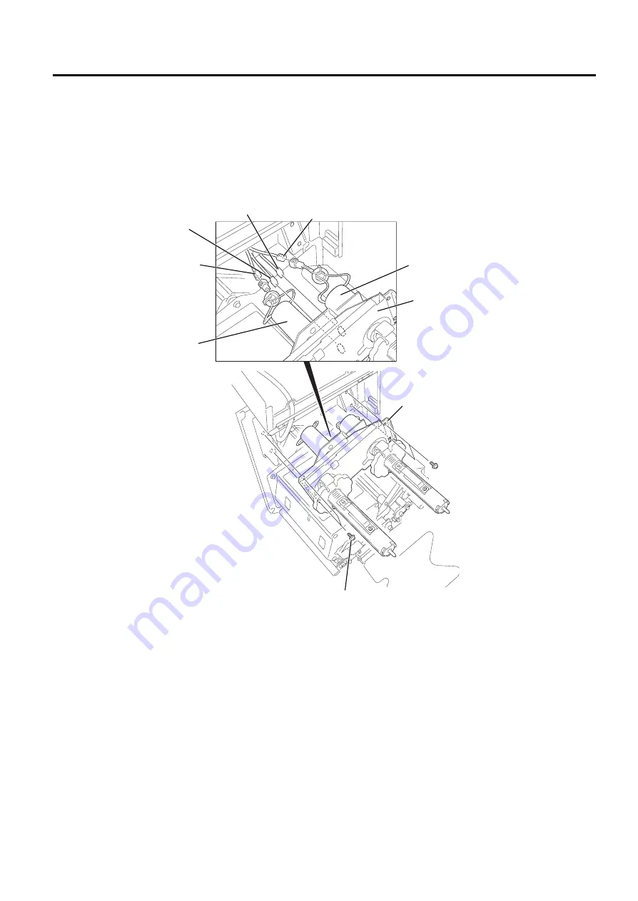
2.8  REPLACING THE RIBBON MOTORS 

1)  Remove the side cover from the printer.  (Refer to Section 2.2.) 
2)  Remove the four SM-4x10 screws which secure the ribbon motor unit to the printer.  
3)  Disconnect the ribbon motor harnesses and slit sensor harnesses from the ribbon motor unit, and 

remove the ribbon motor unit from the printer.  


Ribbon Motor Unit 

Ribbon Motor Unit 

SM-4x10 Screw 

SM-4x10 Screw 

Slit Sensor Harness 
(White, 3 pins) 

Slit Sensor Harness 
(Black, 3 pins) 

Ribbon Motor Harness 
(Red, 2 pins) 

Ribbon Motor Harness 
(Black, 2 pins) 

Fig. 2-16 

Ribbon Motor (Feed) 

Ribbon Motor (Rewind) 

Содержание B-490 SERIES

Страница 1: ...PRINTED IN JAPAN TEC Barcode Printer B 490 SERIES Document No EO18 33011 Original Sep 2001 Revised Maintenance Manual...

Страница 2: ...s and to insure proper performance and operation 2 Failure to follow manual instructions or any unauthorized modification substitution or change to this product will void the limited product warranty...

Страница 3: ...REPLACING THE PLATEN 2 15 2 12 REPLACING THE FEED ROLLER PRINT BLOCK 2 16 2 13 REPLACING THE FEED ROLLER STRIP BLOCK 2 17 2 14 RELACING THE PINCH ROLLER PRINT BLOCK 2 18 2 15 REPLACING THE PINCH ROLLE...

Страница 4: ...unction Selection 6 23 6 5 16 KB 80 Optional Keyboard Connect Setting 6 24 6 5 17 Ribbon Near End Setting 6 24 6 5 18 Expansion I O OUT1 Signal Function Setting 6 25 6 5 19 Expansion I O Signal Level...

Страница 5: ...6 6 13 2 Time Setting 6 56 6 13 3 Battery Voltage Check Setting 6 57 7 ON LINE MODE 7 1 7 1 THRESHOLD SETTING 7 1 8 PRINTER OPERATION 8 1 8 1 OVERVIEW 8 1 8 2 INSTALLING THE PRINTER DRIVERS 8 1 8 2 1...

Страница 6: ...1 Open the carton 2 Unpack the accessories from the carton 3 Unpack the pads and the printer from the carton Fig 1 1 Unpacking Instruction Top Pad PSU Top Pad Owner s Manual CD ROM Side Pad 2 B 492 Pr...

Страница 7: ...y unit Back tension to the label must be around 300g as excessive back tension may affect the label feed accuracy 2 Also this printer does not include a label s backing paper take up unit Backing pape...

Страница 8: ...secured with the cable band together with the I O harness to CN8 on the CPU PC board 4 Write down the starting date of the lithium battery use on the battery sticker for the indication of replacement...

Страница 9: ...roper kind of oil to each part in which lubrication is needed Although the frequency of lubrication varies according to how often the machine is used as a minimum it is necessary to lubricate before a...

Страница 10: ...ss of the fan motor attached to the side cover from CN2 on the I O PC board for the R type disconnect from CN4 Then remove the side cover from the printer 3 Open the top cover 4 Turn the head lever an...

Страница 11: ...stopper from the ribbon shaft ribbon rewind side 3 Remove the two SMW 4x8 screws and disconnect the harness from CN1 on the RSV PC board to detach the solenoid unit from the printer 4 Remove the two...

Страница 12: ...er to close the print head 9 Install the solenoid ass y adjusting the print head position in the following procedure Fig 2 6 Solenoid Spring Pin Head Up Link 9 83 867 62 12 21 25 725 RESTART key PAUSE...

Страница 13: ...aten is 0 5 to 1 0 mm and distances A and B are equal Moving the solenoid ass y in the direction of black arrow causes the print head position higher Moving the solenoid ass y in the direction of whit...

Страница 14: ...print quality Refer to Section 6 7 If the print quality is poor or the ribbon wrinkles fine adjust the print head position by loosening the SM 4x8 and SM 3x6 screws and then perform a print test agai...

Страница 15: ...esses from the CPU PC board CN4 10 12 13 15 16 501 601 to 603 NOTE The printer with the serial number of 3Txxxxxx or later is provided with the battery for the real time clock Disconnect the battery h...

Страница 16: ...is set properly If not refer to the following table and change the settings No Status Function Remarks OFF B 492L type 1 ON B 492R type Selection between L type and R type See CAUTION below OFF Stand...

Страница 17: ...t the ribbon sensor can detect the ribbon Then turn the power on 2 Turn the VR1 on the I O PC board so that the voltage between the GND Frame Plate Refer to the figure on the previous page and TP1 is...

Страница 18: ...PU PC board from the printer Refer to Section 2 5 3 Disconnect the harness from the Expansion I O PC board 4 To detach the Expansion I O PC board remove the two B 3x6 screws which secure the Expansion...

Страница 19: ...ibbon motor unit to the printer 3 Disconnect the ribbon motor harnesses and slit sensor harnesses from the ribbon motor unit and remove the ribbon motor unit from the printer Ribbon Motor Unit Ribbon...

Страница 20: ...rews pushing the motor pinion gear against the slit gear Rewind Lastly remove the backing paper NOTES 1 After installing the ribbon motors check that there is proper back lash between the motor pinion...

Страница 21: ...ess from the stepping motor 5 Remove the two SM 4x8 screws loosen the two belts from the pinion gear and remove the stepping motor 6 When replacing the stepping motor place the platen belt first then...

Страница 22: ...r to Section 2 2 3 Carefully pull out the media guide plate from the two guide shafts 4 Remove the I O PC board Refer to Section 2 6 5 Disconnect the harness from the stepping motor 6 Remove the two S...

Страница 23: ...crew and SMW 4x8 screw to detach the holder plate and platen holder 4 Remove the platen belt to detach the platen 5 Replace the platen with a new one Then put the platen belt on the platen and install...

Страница 24: ...B 4 Remove the SMW 3x6 screw and SMW 4x8 screw to detach the holder plate feed roller holder and feed roller 5 Replace the feed roller with a new one Then put the belt on the feed roller and install...

Страница 25: ...plate Refer to Section 2 2 2 Remove media guide plate from printer Refer to Section 2 10 3 Remove the locking screw to detach the paper guide B 4 Remove the two SMW 3x6 screws to detach the holder pl...

Страница 26: ...printer Refer to Section 2 10 3 Remove the side cover Refer to Section 2 2 4 Remove the I O PC board Refer to Section 2 6 5 Remove the stepping motor strip block Refer to Section 2 10 6 Remove the SMW...

Страница 27: ...2 19 Fig 2 27 9 Pull out the pinch roller ass y from the printer 10 Remove the E 4 E ring and shaft to detach the pinch roller 11 After replacing the pinch roller with a new one then reassemble the pr...

Страница 28: ...n 2 2 2 Push the pinch roller release lever toward the front of the printer to release the strip pinch roller unit 3 Remove the screw to detach the spring and the pinch roller shaft Then pull out the...

Страница 29: ...de cover Refer to Section 2 2 4 Remove the CPU PC board Refer to Section 2 5 5 Disconnect the two harnesses from the media sensor 6 Remove the SMW 3x6 screw to detach the sensor holder and sensor knob...

Страница 30: ...open the ribbon shaft holder plate Refer to Section 2 2 2 Remove the E 3 E ring and two W 3 washers to remove the ribbon back tension block At this time remove the back tension stopper and ribbon back...

Страница 31: ...ness from CN2 and DC power cable from CN4 on the PS unit respectively 3 Remove the SMW 4x6 screw which secure the DC power cable s ground wire to release the DC power cable from the PS unit CAUTION Re...

Страница 32: ...ssemble the printer in the reverse order of removal SMW 4x6 Screw SMW 4x6 Screw Reactor PSU Base PS Unit Fig 2 34 SMW 4x6 Screw WARNING Pass the reactor harness inlet harness and DC power cable throug...

Страница 33: ...Refer to Section 6 4 1 Remove the side cover from the printer Refer to Section 2 2 2 Disconnect the battery harness from CN8 on the CPU PC board Cut the cable band that secures the battery harness to...

Страница 34: ...the battery sticker for the indication of replacement Refer to section 1 3 7 After replacing the battery with a new one reassemble in the reverse order of removal NOTE When securing the battery harnes...

Страница 35: ...rd For the R type disconnect the fan motor harness from CN4 Then remove the side cover from the printer 3 Remove the SMW 3x6 screw to detach the PCMCIA blind plate from the PCB frame NOTE Retain the P...

Страница 36: ...n the PCMCIA PC board to CN7 on the CPU PC board directly and put them together with the locking support 6 Secure the PCMCIA PC board to the two PCB attachment plates with the enclosed SMW 3x6 screws...

Страница 37: ...PC board or operation panel Replace the operation panel harness Poor printing 1 Poor media quality 2 Dirty print head 3 The print head is not set completely Use the media approved by TOSHIBA TEC Clea...

Страница 38: ...ribbon Refer to Section 2 6 and adjust the ribbon sensor Replace the ribbon sensor Replace the I O PC board Label feed failure 1 Media is not set properly 2 Poor media quality 3 Improper adjustment of...

Страница 39: ...e entire inside of the printer should be cleaned 2 Wipe the platen with a cloth moistened with alcohol 3 Clean the print head elements with the TOSHIBA TEC approved print head cleaner Please instruct...

Страница 40: ...sing the following procedure 1 Open the top cover and ribbon shaft holder plate Refer to Section 2 2 2 Carefully pull out the media guide plate from the two guide shafts 3 Detach the paper guide holde...

Страница 41: ...ols to indicate the printer s status Up to 16 characters can be displayed There are three LEDs on the Operation Panel LED Illuminates when POWER The printer is turned on ON LINE The printer is ready t...

Страница 42: ...sion and revision 4 Though turning the power on while holding the FEED and RESTART keys causes the printer to enter the System Mode Reset mode and Dump mode are not accessible This is the start of the...

Страница 43: ...he number of unprinted labels See NOTE 2 3 Press and hold the RESTART key for 3 seconds or longer 4 Press the PAUSE key The data sent from the computer will be cleared and the printer returns to an id...

Страница 44: ...ppears 6 4 1 Ribbon Type Selection Press the PAUSE key The ribbon type can be selected NO RIBBON No ribbon TRANS Transmissive ribbon or NO TRANS Non transmissive ribbon After selecting the ribbon type...

Страница 45: ...RBN FW 8 RBN BK 0 RBN BK 0 PO SPEED 0 PO SPEED 0 X ADJ 0 0mm THRESHOLD R 1 0V THRESHOLD T 0 7V FONT PC 850 0 CODE AUTO RIBBON TRANS SPEED 9600 DATA LENG 8 PARITY EVEN CONTROL XON READY AUTO MESSAGE EN...

Страница 46: ...r 2 If the print distance is 5 5m or less it is rounded down and no data is added to the memory at power off 3 If the count is 31 or less it is rounded down and no data is added to the memory at power...

Страница 47: ...a length 7 7 bits 8 8 bits 26 Parity NON None ODD ODD EVEN EVEN 27 Transmission control code XON XOFF XON XOFF READY BUSY READY BUSY DTR XON READY AUTO XON XOFF READY BUSY DTR XON XOFF AUTO XON XOFF R...

Страница 48: ...ilable OFF Unavailable 47 Function of the expansion I O OUT1 signal TYPE1 Printing TYPE2 End of printing 48 Expansion I O OUT1 signal level LOW Active Low HIGH Active High 49 Function of the expansion...

Страница 49: ...t number Checksum PROGRAM B 492 20SEP2001 V1 0 A FMRM0067001 1A00 2 Boot Check Model Name Date Version Part Number Checksum BOOT B 492 01SEP2001 V1 0 A FMRM0066901 8500 3 Alphanumeric Font ROM Check F...

Страница 50: ...61 to 1408 5 1171 to 1218 2 1314 to 1360 6 1124 to 1170 3 1266 to 1313 7 1076 to 1123 OK Data in the check area can be properly read written NG Data in the check area cannot be properly read written E...

Страница 51: ...t has no problem NG The circuit has a problem or loopback jig is not attached Expansion I O PC board OK The connector has no problem NG The connector has a problem or loopback jig is not attached DIN...

Страница 52: ...rint head If there is no problem with the print head the print head check is complete Press the PAUSE key to return to 1 DIAG Vx x If there is a problem with the print head the following message is di...

Страница 53: ...Y FEED RIBBON TRANS EURO CODE B0 AUTO HD CHK OFF ACK BUSY TYPE1 WEB PRINTER OFF RBN NEAR END 70 KB80 CONNECT OFF Character code selection Zero font code selection Baud rate selection Data length selec...

Страница 54: ...PAUSE key After selecting the character code press the PAUSE key NOTES 1 Use the FEED or RESTART key to select a desired option 2 When pressing the FEED and RESTART keys at the same time in the param...

Страница 55: ...6 SYSTEM MODE EO18 33011 6 5 PARAMETER SETTING 6 15 PC 850 PC 8 PC 852 PC 857 PC 851 PC 855...

Страница 56: ...6 SYSTEM MODE EO18 33011 6 5 PARAMETER SETTING 6 16 PC 1250 PC 1251 PC 1252 PC 1253 PC 1254 PC 1257...

Страница 57: ...icate zero between 0 and When 2 PARAMETER SET appears press the PAUSE key twice After selecting the zero font code press the PAUSE key 6 5 3 Baud Rate Selection With this parameter you can select the...

Страница 58: ...METER SET appears press the PAUSE key 5 times After selecting the parity press the PAUSE key 6 5 6 Transmission Control Code Selection With this parameter you can select the transmission control code...

Страница 59: ...er turns to High level READY At the power off time the printer does not output XOFF 4 XON XOFF At the power on time the printer outputs XON At the power off time the printer does not output XOFF 5 REA...

Страница 60: ...computer 2 Selecting Manual enables you to set the control code When CODE MANUAL is selected and the PAUSE key is pressed the LCD display will show the setting screen of CONTROL CODE1 to CONTROL CODE...

Страница 61: ...onsiders transmissive part as Ribbon and non transmissive part as Ribbon end Non transmissive ribbon The ribbon end sensor considers non transmissive part as Ribbon and transmissive part as Ribbon end...

Страница 62: ...on With this parameter you can select whether or not the Auto Print Head Check function is activated at the power on time When 2 PARAMETER SET appears press the PAUSE key 13 times NOTE It is recommend...

Страница 63: ...ccurs with the Centronics interface communication change the types 6 5 15 Web Printer Function Selection With this parameter you can select whether or not the B 492 printer can be used as a web printe...

Страница 64: ...ameter effective the KB 80 optional keyboard is required 6 5 17 Ribbon Near End Setting With this parameter you can select the condition of ribbon near end detection When 2 PARAMETER SET appears press...

Страница 65: ...ess the PAUSE key 19 times After selecting the OUT1 signal level press the PAUSE key 6 5 20 Expansion I O Inline Mode Function Setting With this parameter you can select the inline mode function of th...

Страница 66: ...tains the following 3 ADJUST SET FEED ADJ 0 0mm BACK ADJ 0 0mm X ADJUST 0 0mm TONE ADJ T 0 TONE ADJ D 0 RBN ADJ FW 0 RBN ADJ BK 0 THRESHOLD R 1 0V THRESHOLD T 1 4V PAUSE PAUSE DIS ADJ 0 0mm PAUSE PAUS...

Страница 67: ...econds or longer in the Printer Parameter Fine Adjustment the key is entered continuously 3 A changed parameter becomes enabled by pressing the PAUSE 4 Use the FEED or RESTART key to select a desired...

Страница 68: ...ins unchanged even if the subsequent fine adjustment is performed 6 6 2 Strip Position Fine Adjustment With this parameter you can fine adjust the strip position When 3 ADJUST SET appears press the PA...

Страница 69: ...0 0mm When the value reached the maximum the value remains unchanged even if the subsequent fine adjustment is performed 6 6 3 Back Feed Length Fine Adjustment With this parameter you can fine adjust...

Страница 70: ...ins unchanged even if the subsequent fine adjustment is performed 6 6 4 X Axis Fine Adjustment With this parameter you can fine adjust the print position on X Axis When 3 ADJUST SET appears press the...

Страница 71: ...ue reaches the coordinate 0 the value remains unchanged even if the subsequent fine adjustment is performed in the negative direction 3 This adjustment cannot be used in the Self Test mode or Test pri...

Страница 72: ...fine adjustment value equals to the sum of the fine adjustment values set by the PC command and this parameter The maximum print tone fine adjustment value is 10 The following table shows the maximum...

Страница 73: ...the fine adjustment press the PAUSE key NOTES 1 The fine adjustment value equals to the sum of the fine adjustment values set by the PC command and this parameter The maximum ribbon motor voltage fine...

Страница 74: ...performed See Section 7 1 Threshold Setting 6 6 8 Strip Motor Driving Speed Fine Adjustment With this parameter you can fine adjust the Strip motor driving speed When 3 ADJUST SET appears press the P...

Страница 75: ...llowing RESTART FEED RESTART FEED RESTART FEED RESTART FEED RESTART FEED RESTART FEED RESTART FEED RESTART FEED RESTART FEED PAUSE PAUSE PAUSE PAUSE PAUSE PAUSE PAUSE PAUSE PAUSE ISSUE COUNT 1 PRINT S...

Страница 76: ...f any error occurs an error message appears and the printer stops printing After clearing the errors press the PAUSE key to return to the System Mode menu The printer does not restart printing automat...

Страница 77: ...paper and the Transmissive Sensor Feed Gap Sensor is for label Ribbon Type Selection Select the ribbon type for the test print from NO RIBBON TRANS or NO TRANS After selecting the printing mode press...

Страница 78: ...s the display to show the values quickly and continuously To stop it release the key Paper Feed Selection Select whether or not a paper feed is performed prior to a test print After selecting the pape...

Страница 79: ...press the PAUSE key to start printing the slant line patterns 1 dot After printing is completed the display returns to 4 TEST PRINT Pressing the PAUSE key causes the display to show SLANT LINE 1DOT ag...

Страница 80: ...key causes the display to show SLANT LINE 3DOT again Then press the FEED key Print Sample of Slant Line 3 dots 6 7 5 Characters While selecting the Characters press the PAUSE key to start printing th...

Страница 81: ...lay to shown BARCODE again Then press the FEED key Print Sample of Barcodes 6 7 7 Non Printing While selecting the Non printing press the PAUSE key to start issuing a blank media After printing is com...

Страница 82: ...type Black mark or Feed gap sensor Ribbon type Transmissive ribbon 2 When the feed gap sensor is selected a gap length is 3 mm Print method Thermal transfer Issue mode Batch printing Label length 76...

Страница 83: ...etting in this mode In case further adjustment is required refer to Section 6 6 Printer Parameter Fine Adjustment to make the threshold fine adjustment 3 When pressing the FEED and RESTART keys at the...

Страница 84: ...e current black mark sensor status 6 8 2 Black Mark Sensor Adjustment Follow the Black mark sensor adjustment procedure below 1 Load a tag stock in the B 492 printer so that the Black Mark Sensor dete...

Страница 85: ...RESTART or FEED key for more than 3 seconds 3 Press the PAUSE key to show the current Feed Gap Sensor status with no paper 6 8 5 Feed Gap Sensor Adjustment No Paper Follow the Feed Gap Sensor no paper...

Страница 86: ...When 6 RAM CLEAR appears press the PAUSE key Select the RAM Clear menu among No RAM Clear Maintenance Counter Clear or Parameter Clear NOTES 1 To exit the RAM clear menu selection press the FEED and...

Страница 87: ...nitial Value Label distance covered 0 km Print distance 0 km Head up down count 0 time Ribbon motor drive time 0 hour RS 232C hardware error count 0 time System error count 0 time Momentary power fail...

Страница 88: ...out slash Control code AUTO Baud rate 9600 bps Data length QP 8 bits QQ 7 bits Parity QP None QQ EVEN Transmission control code QP XON XOFF READY BUSY QQ READY BUSY Ribbon save ON Feed key function FE...

Страница 89: ...ED key 7 times The printer is at the start of the IP Address Setting menu When 7 IP ADDRESS appears press the PAUSE key PRINTER IP ADRES is selected Then press the PAUSE key to set the IP address Set...

Страница 90: ...ng screen of the socket port number Set the number for each digit with the RESTART and FEED keys and then move the cursor to the next digit with the PAUSE key After the last digit is set press the PAU...

Страница 91: ...to enter the Dump Mode 5 Select the receive buffer to be dumped with the FEED or RESTART key 6 Press the PAUSE key to start printing The printer prints the data in the selected receive buffer 7 After...

Страница 92: ...30 2C 31 31 30 30 2C 30 0 D0760 1100 0 37 34 30 7C 7D 7B 43 7C 7D 7B 4C 43 3B 30 30 33 740 C LC 003 30 2C 30 30 32 30 2C 30 30 33 30 2C 30 36 36 30 0 0020 0030 0660 2C 30 2C 32 7C 7D 7B 4C 43 3B 30 3...

Страница 93: ...ys at the same time turn on the printer Hold both keys until the 1 DIAG Vx x Message appears Press the FEED key 8 times The printer is at the start of the BASIC setting menu When 9 BASIC appears press...

Страница 94: ...key twice 00 TEST BAS 01 TEST DAT 00 TEST BAS FILE MAINTENANCE Program file is displayed RESTART PAUSE RESTART Data file is displayed Data files in the BASIC file area are displayed each time the REST...

Страница 95: ...is displayed 4 Press the RESTART key and the display shows 9 RTC SET 5 When the PAUSE key is pressed the date setting display appears 6 Setting item can be selected by pressing the RESTART or FEED ke...

Страница 96: ...ar 6 13 2 Time Setting 1 Press the PAUSE key when the display is shown below then the time can be set 2 The cursor is displayed under the Hour Change the number for the Hour with the FEED or RESTART k...

Страница 97: ...rformed can be set 2 Select ON or OFF with the FEED or RESTART key 3 After selection press the PAUSE key The display will show the date that has been just set 4 When the FEED and RESTART keys are pres...

Страница 98: ...interfere with this process causing paper jam errors To get around this problem a minimum threshold can be set for the sensor in the following way Threshold setting procedure 1 Turn the power ON The...

Страница 99: ...eed more than 1 5 labels may result in an incorrect threshold setting 3 While the Print Head Block is raised the PAUSE key does not work 4 Errors such as paper end and cutter error are not detected du...

Страница 100: ...ot density of 305 DPI As the paper is advanced through the printer by the paper feed mechanism the thermal head continuously prints the image as a series of dot lines at a resolution of 305 dots per i...

Страница 101: ...95 Windows 98 Windows NT and Windows 2000 are registered trademarks of Microsoft Corporation Pentium is a registered trade mark of Intel Corporation 8 2 2 Driver Installation NOTES 1 How to install th...

Страница 102: ...o the Software License Agreement screen NOTE If you click on the No button in the License Agreement screen the program will not be installed 7 Carefully read the Software License Agreement To accept t...

Страница 103: ...ou selected the Local Printer in the previous step go to Step 10 If you selected the Network Printer in the previous step go to Step 11 10 When you selected the Local Printer in Step 9 select the PC p...

Страница 104: ...the same name as already installed printer that printer will be overwritten When you desire to install the same printer for many times change the printer name each time 13 Upon clicking on the Next bu...

Страница 105: ...ON EO18 33011 8 2 Installing the Printer Drivers 8 6 15 After the TEC Printer Driver has been successfully loaded the Printers screen should appear as shown below showing the TEC B 492 as being succes...

Страница 106: ...con 2 Select TEC B 492 Printer and click on the Add Remove button 3 When the following screen appears click on the Yes button 4 When the Registration information deletion screen appears click on the Y...

Страница 107: ...screen of Step 7 will appear instead 6 Upon clicking on the Yes To All button the following screen appears to confirm the deletion of shared file Click on the Yes button NOTE Deleting the shared file...

Страница 108: ...will allow downloading firmware updates to the B 492 printer 9 2 INSTALL PROGRAM INSTALLATION Before you can communicate from your PC to the B 492 printer you must first copy the Install Program for B...

Страница 109: ...Installation Procedure 1 While running Windows 95 or Windows 98 insert Setup Disk 1 2 into the PC floppy drive 2 Click on the START button then highlight RUN and click on RUN 3 When the RUN display a...

Страница 110: ...e screen appears Click on the button to accept the directory or change the directory if desired 7 The following program group selection menu will appear Click on the CONTINUE button 8 When the install...

Страница 111: ...e mode or System mode 2 For the Centronics communication program downloading takes about 3 minutes in the Main section and a few seconds in the Boot section respectively For the RS 232C communication...

Страница 112: ...en display below 5 As soon as you click on B NX Program Loader the screen will change as shown below 6 Select the drive directory file name extension and applicable PC port for the firmware to be inst...

Страница 113: ...t this time the printer is in the ON LINE mode To finish the program download click on the END button If you want to perform the program download to other printers change the printer and start it up i...

Отзывы: