57
13. SYSTEM menu
13-1-1. Individual channel settings
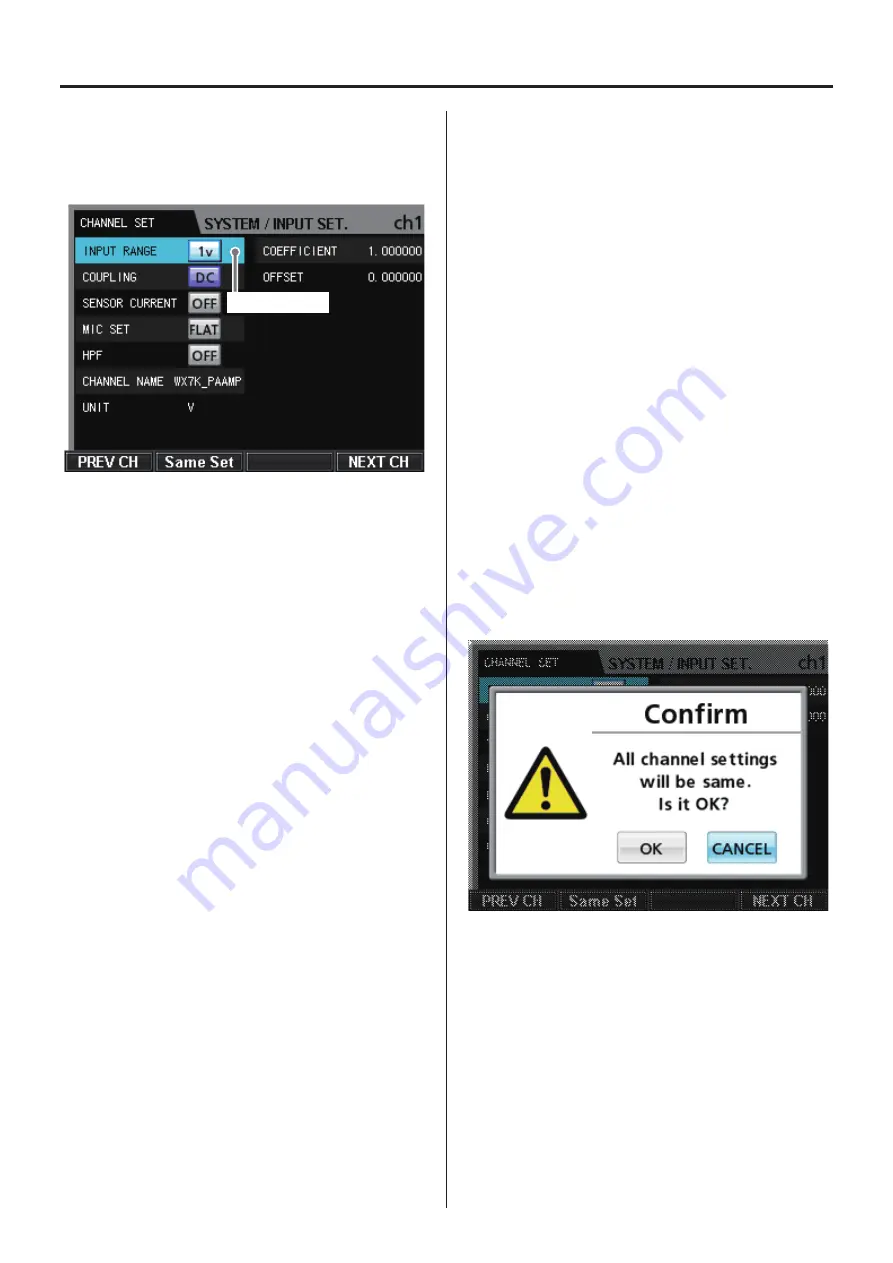
On the INPUT SETTING screen, press the VALUE knob to open the
setting screen for the selected channel.
Current selection
o
To return to the SYSTEM menu, press the MENU or CANCEL but-
ton on the front panel.
o
If you want all channels to have the same settings, after confirm-
ing the set values, press the VALUE knob while pressing and
holding the SHIFT button.
o
The COEFFICIENT and OFFSET values are recorded as information
in header files. They do not affect the display, output signals or
recording data of the WX-7000.
Selection
Use the VALUE knob and the up, down, left and right (
5
,
b
,
g
,
t
) buttons to change the selection.
Press the VALUE knob to change the setting of the selected parameter.
INPUT RANGE
The options are 20V, 10V, 5V, 2V, 1V, 0.5V, 0.2V and 0.1V.
COUPLING
The options are DC and AC.
DC: Use when recording signals that include direct currents
AC: Use when recording signals of 1Hz or more
SENSOR CURRENT (PA Current)
Sets the ICP sensor current.
The options are OFF, 4mA and 0.5mA.
MIC SET (weighting network)
The options are FLAT, A and C.
HPF
The options are OFF, 10Hz and 20Hz.
CHANNEL NAME
Sets the name of the channel.
o
A maximum of 20 characters can be used for a channel name.
o
Only the first 10 characters of the channel name are shown on
the CHANNEL SET screen.
o
For instructions about inputting characters, see “12-4. Inputting
characters as setting values” on page 50.
UNIT
Sets the name of the input signal unit.
o
A maximum of 8 characters can be used for a unit name
o
For instructions about inputting characters, see “12-4. Inputting
characters as setting values” on page 50.
COEFFICIENT
Use to apply a coefficient to the measured voltage to convert the
physical quantity. The physical quantity is calculated using the fol-
lowing formula.
Physical quantity = (measured voltage - OFFSET) × COEFFICIENT
OFFSET
Use to subtract an offset amount when calculating the measured
voltage.
o
The offset value can have a maximum of 10 digits, including dig-
its after the decimal place.
o
Only the first 8 digits of the offset value are shown on the
CHANNEL SET screen.
o
For instructions about inputting characters, see “12-3. Inputting
numbers as setting values” on page 50.
PREV CH (F1 button)
Opens the setting screen of the previous channel.
Same Set (F2 button)
Applies the currently shown channel settings to all channels.
Press the F2 button to open a confirmation screen.
Use the VALUE knob and the left and right (
g
,
t
) buttons to
change the selection.
Press the VALUE knob to confirm a selection.
Select “OK” to confirm and apply the same settings to all channels.
NEXT CH (F4 button)
Opens the setting screen of the next channel.
Содержание WX-7000
Страница 1: ...WIDE BAND DATA RECORDER Owner s Manual Z WX 7000 D01190210J ...
Страница 84: ...84 19 Exterior drawings WX 7016 340 348 10 8 220 13 8 123 82 40 15 WX 7032 164 82 40 40 15 ...
Страница 85: ...85 WX 7064 246 82 40 40 40 40 15 WX 7096 360 370 396 19 Exterior drawings ...
Страница 86: ...86 19 Exterior drawings WX 7128 360 370 478 ...


