background image

56

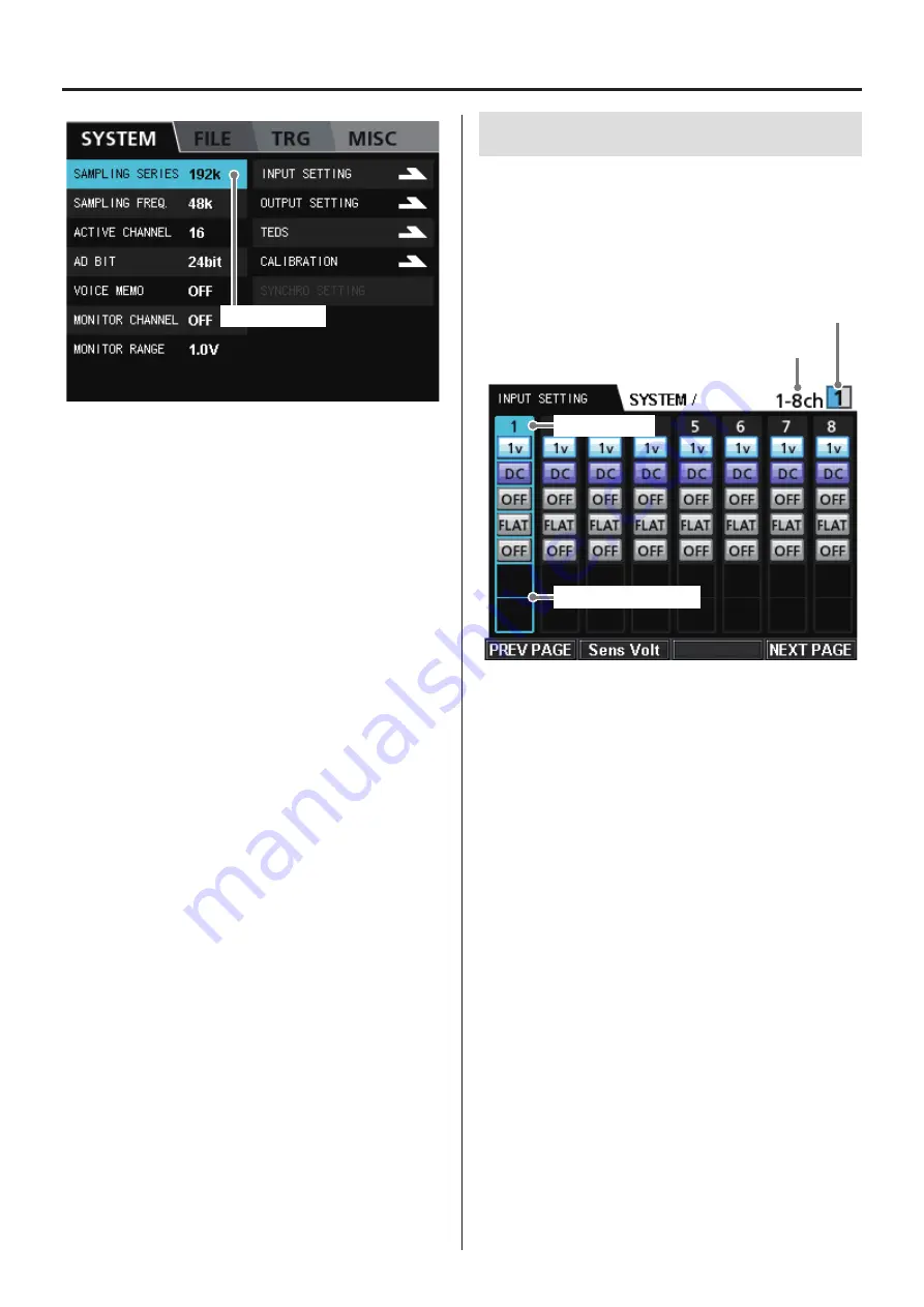
13. SYSTEM menu 

Current selection

For details about the sampling frequency, analog-digital conver-
sion bit depth (AD BIT) and number of recording channels (ACTIVE 
CHANNEL) Parameters, see “Sampling frequencies and bands” on 
page 77 and “Number of channels that can be recorded simulta-
neously” on page 77.

 Selection 

Use the VALUE knob and the up, down, left and right (

5

b

g

t

) buttons to change the selection. 

Press the VALUE knob to change the setting of the selected parameter. 

SAMPLING SERIES

Sets the sampling frequency series. 
The four series options are 192 kHz, 200 kHz, 204.8 kHz and 131.0 kHz. 

 SAMPLING  FREQ.

Sets the sampling frequency. 
The 8 available sampling frequency options correspond to the cur-
rent sampling series. 

AD BIT

Sets the analog-digital conversion bit depth (quantization bits). 
The options are 16-bit and 24-bit. 

ACTIVE CHANNEL

Sets the number of recording channels. 
The options are the possible number of recording channels for the 
current system. 

VOICE MEMO

Turn voice memo recording ON or OFF. 
Voice memos are not recorded during the pre-trigger interval. 
Moreover, the beginnings of voice memos and the beginnings of 
data are aligned when played back, so the timing might be different 
from when recorded. 

MONITOR CHANNEL

Sets the channel monitored. 
The options are the channels available in the current system and OFF. 
Set this to OFF when you do not want to monitor the output. 

MONITOR RANGE

Sets the monitoring output range. 
The setting range is from 1.0 V to 5.0 V in 0.1 V increments.

13-1. INPUT SETTING

From the SYSTEM menu, select the INPUT SETTING item and press 
the VALUE knob to open the INPUT SETTING screen. 
The first channel numbers are shown with their settings beneath 
them. 
Change the channel numbers shown with the F1 (PREV PAGE) and 
F4 (NEXT PAGE) buttons. 

Channels shown

Expansion unit shown

Current selection

Current channel settings 

Channels shown

This shows the range of channels currently shown. 

Expansion unit shown

This shows the number of the expansion unit that has the channels 
currently shown. 

Selection 

Use the VALUE knob and the left and right (

g

t

) buttons to 

change the selection. 
If you move further right from the selection at the right edge of the 
screen, the next page will open. In the same manner, moving left 
from the left edge will open the previous page. 
Press the VALUE knob to change the setting of the selected parameter. 

PREV PAGE (F1 button)

Opens the previous page. 

Sens Volt (F2 button)

Opens the sensor voltage menu screen. 

NEXT PAGE (F4 button)

Opens the next page. 

Содержание WX-7000

Страница 1: ...WIDE BAND DATA RECORDER Owner s Manual Z WX 7000 D01190210J ...

Страница 2: ... input and output 25 Control input and output 25 Status input and output 25 Input and output circuit format 25 Serial communication 25 Connector 25 Pin assignments 25 5 3 AQ VU synchronized recording connector 26 Function 26 Input 26 Control output 26 Serial output 26 Input and output circuit format 26 Input format 26 Output format 26 Connector 26 Pin assignments 26 5 4 EXT TRIGGER IN connector 26...

Страница 3: ...42 10 3 Synchronized recording settings 43 10 4 Synchronized playback settings 43 10 5 Confirming synchronization connections 43 10 6 Checking connections 44 10 7 Adjusting the time 45 10 8 Synchronization status display 45 11 AQ VU synchronized recording 46 11 1 Connections 46 11 2 Turning the units on 46 11 3 Settings 46 11 4 AQ VU synchronized connection settings 47 11 5 Setting the time 47 12 ...

Страница 4: ...terface cards 76 18 Specifications 77 18 1 Recording unit WX 7000 77 Recording media 77 RDX 77 SDHC 77 Sampling frequencies and bands 77 Number of channels that can be recorded simultaneously 77 Recording times 78 Analog monitoring output 80 Voice memo input and output 80 Internal clock 80 External interfaces 80 18 2 Input output unit AU WXEPIO 81 Analog signal input channels 81 Analog signal outp...

Страница 5: ...t development power generation and railways Moreover as the scales of the subjects measured increase the need has arisen for standalone data recorders that have the ability to back up irreplaceable measurement data and that can be operated easily The WX 7000 series of wideband data recorders fulfills these needs These systems use RDX cartridges and SDHC cards as recording media and they can record...

Страница 6: ...include trigger recording and audio playback of recorded voice memos o o Synchronized AQ VU video recording with 4 channel camera possible o o Files are saved regularly preventing data loss due to unexpected power interruptions o o Power outage signals from an uninterruptible power supply UPS can trigger the system to conduct recording conclusion proce dures to prevent data loss o o Panel lock fun...

Страница 7: ...sion units are connected chan nel numbering starts with channel 1 at the top left and ends with the last channel 32 64 96 or 128 at the bottom right WX 7032 32 input and output channels WX 7064 64 input and output channels WX 7096 96 input and output channels 1 Introduction ...

Страница 8: ...from analog to digital binary for mat with a dat file extension Header file Contains recording conditions and other information text format with an hdr file extension o o In addition when voice memos are recorded their files with wav extensions are also saved 1 7 2 File name The file name is common to the data file and header file An ID number is added to the end of the specified file name When yo...

Страница 9: ...ion The byte order is from the lowest to the highest Intel format The data order is from the first sampling channel to the second sam pling channel and so on until the last sampling channel This order is called the INTERLACED format and the format name is recorded in STORAGE_MODE in the header file The structure of a data file is as follows In this document a collec tion of data as shown in the ex...

Страница 10: ...05 8 000000e 005 8 000000e 005 8 000000e 005 8 000000e 005 X_OFFSET 1 0 Y_OFFSET 0 000000e 000 0 000000e 000 0 000000e 000 0 000000e 000 0 000000e 000 0 000000e 000 0 000000e 000 0 000000e 000 NUM_SAMPS 11904000 DATA DEVICE WX 7000 CH1_1 WX7K_PAAMP RANGE 2V AC 4mA FLAT OFF 24V CH2_2 WX7K_PAAMP RANGE 2V AC 4mA FLAT OFF 24V CH3_3 WX7K_PAAMP RANGE 2V AC 4mA FLAT OFF 24V CH4_4 WX7K_PAAMP RANGE 2V DC O...

Страница 11: ...written after the underscore channel number channel name amplifier setting range coupling PA current weighting HPF PA voltage REC_MODE Recording destination device RDX SD PC END_TIME Recording end time START_TRIGGER Recording start conditions COMMAND Interface command LEVEL Level trigger DATE When Repeat Count is 1 in the interval action TIMER When Repeat Count is 2 or more in the interval action ...

Страница 12: ...radio interference in which case the user may be required to take adequate measures Pour les utilisateurs en Europe AVERTISSEMENT Il s agit d un produit de Classe A Dans un environnement domestique cet appareil peut provoquer des interférences radio dans ce cas l utilisateur peut être amené à prendre des mesures appropriées Für Kunden in Europa Warnung Dies ist eine Einrichtung welche die Funk Ent...

Страница 13: ... OUT connector of the unit above with the EXPANSION IN connector of the unit below it using a connection cable o o Place the AC adaptor units away from the AU WXEPIO expansion units o o When using within Japan use the included AC cord that has a PSE mark on the plug o o When using in the North American region use the included AC cord that has a CSA mark on the plug 3 1 1 WX 7016 Included AC adapto...

Страница 14: ... DC IN on the 3rd AU WXEPIO unit from the top and the third adaptor to the 5th unit 3 1 5 WX 7128 Connection cable Included AC adaptor Connect one included AC adaptor to the DC IN on the WX 7000 the second adaptor to the DC IN on the 3rd AU WXEPIO unit from the top the third adaptor to the 5th unit and the fourth adaptor to the 7th unit 3 Connections ...

Страница 15: ... in some cases For complete protection against power outages use an uninterrupt ible power supply UPS for the external power source Have the UPS send a power outage contact signal to the WX 7000 so that it will conduct recording completion procedures Power the WX 7000 through its AC adaptor from a power output from the UPS Connect the UPS power outage contact signal output to the WX 7000 UPS SIGNA...

Страница 16: ...rectly Use a category 7 LAN cable 3 4 TEDS A Transducer Electronic Data Sheet TEDS is a standard format defined in IEEE 1451 4 for recording information specific to a measurement sen sor that is stored within the sensor itself By connecting a TEDS sensor with a TEDS compatible WX 7000 sensor calibration is made unnecessary reducing the time required for measurement preparations o o If transducer i...

Страница 17: ...nput setting PA Input setting AC Input setting DC Piezoelectric accelerometer Electric charge output type 608 Amplifier for piezoelectric accelerometers SA 611 General pressure monitoring type Strain Gauge Pressure Transducer TP HVR TEDS compliant strain DC amplifier SA 570ST Microphone Earphone Oscilloscope or other device 3 Connections ...

Страница 18: ...18 4 Names and functions of parts 4 1 Front panels WX 7000 recording unit G K J I H E F D C A B o o Drive cover open A N M O L AU WXEPIO expansion unit P Q ...

Страница 19: ...use it as an ENTER button Up 5 button Down b button Left g button Right t button Use these to move the cursor When inputting parameters you can also use these to increase or decrease values E STANDBY ON switch Press to turn the power on or put the unit into standby Press the switch up to turn the power on Press it down to put the unit into standby F Transport buttons Stop 8 STOP button Press to st...

Страница 20: ...is being supplied to the RDX docking station Lit green Ready Power is being supplied to the RDX docking station and it is functioning properly Blinking green Ejecting The cartridge is being ejected from the docking station Lit yellow Malfunctioning A malfunction has been detected in the RDX docking station Blinking yellow Ready The RDX media was being accessed when you pressed the EJECT button Aft...

Страница 21: ...y connected by four joint bars The lengths of the joint bars differ for the WX 7016 WX 7032 WX 7064 WX 7096 and WX 7128 models S Built in speaker This outputs voice memos o o When an earphone is connected to the earphone jack no sound is output from this built in speaker 4 Names and functions of parts ...

Страница 22: ...to connect the system with a computer The LED blinks when transmitting data o o Use a category 7 LAN cable D EXPANSION OUT connector Connect this to the EXPANSION IN connector of the AU WXEPIO below it using a connection cable E DIGITAL CONTROL input connector Use to control recording and playback with contact signals and to connect a remote control unit option F SYNC IN connector Use for synchron...

Страница 23: ...ct the desired contact output of an uninteruptible power supply here Confirm the specifications of the connector before hand See page 27 Do not connect anything if you are not using this feature N EXPANSION OUT connector Connect this to the EXPANSION IN connector of the AU WXEPIO below it using a connection cable O EXPANSION IN connector Connect this to the EXPANSION OUT connector of the WX 7000 o...

Страница 24: ...ction 1 GND Ground 2 RESERVED Reserved 3 RESERVED Reserved 4 GND Ground 5 RESERVED Reserved 6 RESERVED Reserved 7 GND Ground 8 GND Ground 9 RESERVED Reserved 10 RESERVED Reserved 11 RESERVED Reserved 12 RESERVED Reserved 13 GND Ground 14 GND Ground 15 RTCADJIN Internal clock adjustment input 16 RECFWDIN REC FWD input 17 STOPIN STOP input 18 RECIN REC input 19 FWDIN FWD input 20 PAUSEIN PAUSE input...

Страница 25: ...A 28S Pin assignments Pin Signal Function 1 GND Power supply 0 V 2 SYNCFS FS clock 3 SYNCFS FS clock 4 GND Power supply 0 V 5 MSYNC Master clock 6 MSYNC Master clock 7 GND Power supply 0 V 8 COM Command signal 9 COM Command signal 10 GND Power supply 0 V 11 STS Status signal 12 STS Status signal 13 GND Power supply 0 V 14 RESERVED Reserved 15 GND Power supply 0 V 16 SYNCTRG SYNC trigger 17 SYNCTRG...

Страница 26: ...CK OUT Sampling clock output 6 S IF IN Reserved 7 GND Ground 8 S IF OUT Internal clock serial output 9 RESERVED 5 4 EXT TRIGGER IN connector Function Use to input external trigger contact signals to start and stop recording Changing from H to L starts recording Changing from L to H stops recording External triggers must be turned on with the trigger setting Input circuit format L level 0 4 V or le...

Страница 27: ...t connector Function If a power outage occurs when using this system with a UPS power supply and a UPS power outage detection contact signal is input here recording closing procedures will be conducted to stop record ing Input circuit format L level 0 4 V or less H level open or 2 V or more Connector Round connector Hirose HR10 7R 4S Pin assignments Pin Signal Function 1 UPS SIGNAL IN Power outage...

Страница 28: ...dropped In order to assure the accuracy and security of data please observe the following precautions o o When purchased new RDX cartridges are NTFS formatted Format cartridges with the WX 7000 before using them with this system o o When not using a cartridge store it in a protective case o o Do not stack RDX cartridges o o Avoid dusty or humid environments o o Avoid direct sunlight high and extre...

Страница 29: ...on pull it out directly If an RDX cartridge cannot be ejected If an RDX cartridge cannot be ejected stop the power supply to the unit and confirm that the EJECT button indicator is unlit If the LCD display is unlit but the RDX docking station EJECT button is lit green stop the power supply to the DC IN or the AC adaptor After confirming that the EJECT button indicator is unlit restart the power su...

Страница 30: ...hand 4 Close the drive cover SDHC card write protection switches SDHC cards have write protection switches Writing prohibited Locked Write protection switch Writing data can be prohibited by moving the switch to the LOCK position Slide the write protection switch to one direction completely o o To use an SDHC card for recording or to erase recording data on it or format it unlock the write protect...

Страница 31: ... status of the system can be changed in the following manner Stopped Record ready Recording Playback ready Playing back Turn power on Waiting for button input or setting 0REC 7FWD 9PAUSE 7FWD 9PAUSE 8STOP Show input signal levels set screen display Show recording and input signal levels set screen display Show playback and output signal levels set screen display Select playback file 7FWD F FWD mRE...

Страница 32: ...can select the COUNT item on the LCD and press and turn the VALUE knob to search by time d Data display These bar meters show the levels of the channels Press the F1 Peak Clear button to reset the peak hold display e Recording file information FILE name of file being recorded DIR name of directory where file is being recorded The information shown changes according to the status of the recording u...

Страница 33: ...hen ready for playback you can select the TIME item on the LCD and press and turn the VALUE knob to search by time o o To set the time select the TIME item on the LCD when stopped and press and turn the VALUE knob j Recording media information When playing back or ready for playback this shows the elapsed time from the beginning of the file At all other times this shows the amount of space used on...

Страница 34: ...display 16 channel display example o o You can also change the number of channels shown using the DISPLAY CH item on the MISC menu 6 Basic operation 6 7 2 Peak indicators Peak indicators are shown when ready to record when recording and when playing back Example Peak Peak o o Peak indicators are reset whenever recording starts from a record ready state o o When recording stops the bar meters disap...

Страница 35: ...ar Resets the peak hold indicators on the Home Screen F2 button Input Amp Opens the INPUT SETTING screen F3 button Output Amp Opens the OUTPUT SETTING screen F4 button Display Unit Changes the unit shown when using a system with 32 or more channels Pressing SHIFT while stopped F1 button No indication No function F2 button TEDS Opens the TEDS setting screen F3 button Calibration Calibrates the syst...

Страница 36: ...ay Unit when pressing and holding the SHIFT button 6 Basic operation Pressing SHIFT while recording F1 button No indication No function F2 button Input Amp confirmation Check the settings on the INPUT SETTING screen F3 button Output Amp confirmation Check the settings on the OUTPUT SETTING screen F4 button Display Unit Changes the unit shown when using a model with 32 or more channels When ready t...

Страница 37: ...t is writing to the media now The unit is reading from the media now This shows the amount of available recording time hours minutes In this example the amount of available recording time is 9 hours 26 minutes o o Select the recording media information and press the VALUE knob to open the FILE screen o o RDX cartridges in NTFS format immediately after purchase for example cannot be used as is with...

Страница 38: ... setting 3 Turn the VALUE knob to change the setting value You can also use the up and down 5 b buttons to change the setting value 4 Press the VALUE knob to confirm the setting The settings of the following items can be changed from the Home Screen For details about each parameter see 12 Settings on page 48 Sampling series SERIES Sampling frequency SAMPLE Analog digital conversion bit depth AD Nu...

Страница 39: ...gger Recording time Post trigger Ready to record Recording starting conditions u level trigger u external trigger u timeout trigger Recording stopping conditions u level trigger u external trigger u Recording time Recording stops For trigger recording you can set a combination of a starting trigger level external or timeout and a stopping trigger level or external Recording starting conditions Lev...

Страница 40: ...g media is full or recording is stopped manually Start time Recording starts at the set time Recording time Recording continues for the set amount of time Interval time If the number of repetitions is set to 2 or more recordings this is the amount of time that the system stays in a record ready state from the time one recording ends until the next recording starts Repetitions Sets the number of re...

Страница 41: ...ng with the counter When ready for playback select the counter COUNT and use the VALUE knob to search for the desired counter position Then press the VALUE knob to start playback from that counter position 9 5 Searching by event When ready for playback select the event number EVENT and use the VALUE knob to search by event number Then press the VALUE knob to start playback from the position of tha...

Страница 42: ...or file Search for file Playback stops 10 Synchronization function 10 1 Connections Master unit Slave unit Synchronization cable o o Use a synchronization cable to connect the master unit SYNC OUT to the slave unit SYNC IN o o When not using synchronized operation do not connect the syn chronization cable o o Always turn the master unit and slave unit off before connecting or disconnecting a synch...

Страница 43: ... kHz About 25 seconds o o Level triggers become effective 10 seconds after the unit becomes record ready 10 4 Synchronizedplaybacksettings After selecting the file to play on the slave unit select the file to play on the master unit If you select the file to play on the master unit first search by ID for the file to play on the slave unit o o It is not possible to search the slave unit using metho...

Страница 44: ...nection status Select OK in the dialog box and press the VALUE knob If the connection is confirmed to be okay the connection status of the master and slave units will be shown as OK o o The slave unit does not have a CONNECT CHECK option Connection status If the connection check conducted on the master unit completes successfully the connection status of the slave unit will be shown as OK ...

Страница 45: ...nit to the time of the master unit 1 second discrepancy 10 8 Synchronization status display When synchronization connection is in use the synchronization sta tus is shown on the HOME screen Synchronization status Synchronization status Master unit Slave unit Synchronization not working Synchronization working When synchronized recording or playback starts if synchronization fails an error message ...

Страница 46: ...CHRO to ON on the AQ VU SETTING screen o o The clocks of the main unit and the AQ VU are not synchronized automatically Manually synchronize them on the ADJUST TIME screen o o To synchronize operation with the main unit connect the AQ VU only to the master unit Do not connect it to a slave unit o o AQ VU synchronization cannot be used with 204 8kHz sampling o o When not using the AQ VU set AQ VU s...

Страница 47: ...o Before setting the time set AQ VU SYNCHRO to ON Press F2 ADJUST TIME to synchronize the time of the AQ VU to that of the main unit 1 seconds 11 4 AQ VU synchronized connec tion settings From the main unit SYSTEM menu select AQ VU SETTING and press the VALUE knob to open the AQ VU SETTING screen Press the VALUE knob again Set AQ VU SYNCHRO to ON ...

Страница 48: ...o use the up down left and right 5 b g t buttons to change the selected item 3 Press the VALUE knob If you select an item that has its current value shown to its right a list of values opens and you can change the selected item s setting The following screen shows an example of a selection from the setting value options For instructions see 12 2 Selecting val ues from setting options on page 49 o ...

Страница 49: ...o set a different value for a parameter such as the sampling fre quency press the VALUE knob to show a list of options to the right of the current setting value Current selection Turn VALUE knob to change Current setting 1 Turn the VALUE knob to select the value you want to set Turn it clockwise to move down the list Turn it counterclockwise to move up the list You can also use the up and down 5 b...

Страница 50: ...l changing a setting 12 4 Inputting characters as setting values To input characters as a setting value such as a CHANNEL NAME press the VALUE knob to open the character input screen The currently set characters are shown in the window near the top of this screen 1 Turn the VALUE knob to select the position where you want to input a character and press the VALUE knob e o o You can also use the up ...

Страница 51: ...creen item list Sampling series SERIES Sampling frequency SAMPLE Analog digital conversion bit depth AD Number of recording channels REC CH Fan activation FAN Voice memo activation MEMO Monitoring output channel Searching by ID ID during playback Searching by event EVENT during playback Searching with the counter COUNT during playback Searching by time TIME during playback Trigger settings TRG Dev...

Страница 52: ...NG Output settings OUTPUT SETTING TEDS setting TEDS Calibration CALIBRATION AQ VU SETTING IRIG GPS SETTING 1 2 16 ICP voltage Sens Volt Input range INPUT RANGE Coupling COUPLING ICP current SENSOR CURRENT Weighting network MIC SET High pass filter HPF Channel name CHANNEL NAME Unit UNIT Coefficient COEFFICIENT Offset OFFSET Output range 1 2 16 Output unit setting OutUnit Set TEDS loading screen Ma...

Страница 53: ...ggers NONE Trigger recording TRIGGER Interval recording INTERVAL Starting trigger START CONDITION Pre trigger setting PRE TRG Stopping trigger STOP CONDITION Post trigger setting POST TRG Repetitions REPEAT COUNT Starting time START TIME Recording time REC TIME Interval time INTERVAL Repetitions REPEAT COUNT Level trigger LEVEL External trigger EXTERNAL Time out trigger TIMEOUT Level trigger LEVEL...

Страница 54: ...itialization PARAMETER Speaker output setting SPEAKER Fan activation FAN Sampling notation setting NOTATION Language setting LANGUAGE Network settings NETWORK Date and time settings TIMESET Display adjustment LCD Beep settings BEEP Show version information VERSION Button operation sound BUTTON BEEP Warning sound WARNING BEEP 12 Settings ...

Страница 55: ...NIT V 8 ASCII characters maximum All channels COEFFICIENT 1 00000000 10 ASCII characters maximum All channels OFFSET 0 00000000 10 ASCII characters maximum All channels SENSOR VOLTAGE 28V 24 28V All expansion units OUTPUT RANGE 1V 1 0 5 0 V in 0 1V increments All channels OUTPUT UNIT UNIT 1qUNIT 1 UNIT 2qUNIT 2 UNIT 3qUNIT 3 UNIT 4qUNIT 4 UNIT 5qUNIT 5 UNIT 6qUNIT 6 UNIT 7qUNIT 7 UNIT 8qUNIT 8 DEV...

Страница 56: ... played back so the timing might be different from when recorded MONITOR CHANNEL Sets the channel monitored The options are the channels available in the current system and OFF Set this to OFF when you do not want to monitor the output MONITOR RANGE Sets the monitoring output range The setting range is from 1 0 V to 5 0 V in 0 1 V increments 13 1 INPUT SETTING From the SYSTEM menu select the INPUT...

Страница 57: ... o o Only the first 10 characters of the channel name are shown on the CHANNEL SET screen o o For instructions about inputting characters see 12 4 Inputting characters as setting values on page 50 UNIT Sets the name of the input signal unit o o A maximum of 8 characters can be used for a unit name o o For instructions about inputting characters see 12 4 Inputting characters as setting values on pa...

Страница 58: ...E knob to open the OUTPUT SETTING screen Current selection Channels shown Expansion unit shown channel number OUTPUT RANGE o o To return to the SYSTEM menu press the MENU or CANCEL but ton on the front panel o o If you want all channels to have the same settings after confirm ing the set values press the VALUE knob while pressing and holding the SHIFT button Selection Use the VALUE knob and the up...

Страница 59: ... For example after recording numerous channels at a measurement site when playing back data on a system with fewer channels you will need to select from among the numerous channels of recorded data for analog output from the playback system Setting example 1 When using a WX 7016 system to play back a 128 channel file recorded using a WX 7128 system in order to play back data recorded on channels 6...

Страница 60: ...checked F4 button Select all channels that have TEDS data loaded 13 3 1 Loading TEDS data If a TEDS sensor is connected after the power has already been turned on the TEDS data will not appear on the screen automati cally Press the F3 button to reload TEDS data The following screen appears while the TEDS data is being loaded 13 3 2 Calibrated value settings To set calibrated value for TEDS data se...

Страница 61: ...In the SYSTEM menu select TEST SIGNAL OUT and press the VALUE knob to open a confirmation screen Select the OK button and press the VALUE knob to start calibration 13 4 2 Test signal output Select TEST SIGNAL OUT and push the VALUE knob To change the test signal output use the VALUE knob to select the desired output Press Output START F2 to output the test signal Press Output STOP F2 to stop test ...

Страница 62: ...2 13 6 AQ VU settings See 11 AQ VU synchronized recording on page 46 14 FILE settings Current selection Media information Selection Use the VALUE knob and the up down left and right 5 b g t buttons to change the selection Press the VALUE knob to change the setting of the selected parameter ...

Страница 63: ...ted according to the set sampling frequency bit depth and number of recording channels DIR The name of the directory where recorded data is saved FILE The prefix given to the names of recording data files 14 2 New file settings In the FILE menu select RECORDING FILE and press the VALUE knob to open the RECORDING FILE screen Current selection 14 2 1 DEVICE Select the media where recording files are...

Страница 64: ...ns about inputting characters see 12 4 Inputting characters as setting values on page 50 o o Lowercase letters cannot be used in file names 14 2 4 Comment Sets the recording file comment o o For instructions about inputting characters see 12 4 Inputting characters as setting values on page 50 14 3 Opening files In the FILE menu select FILE OPEN and press the VALUE knob to open the FILE OPEN screen...

Страница 65: ...n 14 5 Selecting files Selected file number Total number of files Current directory Current selection On this screen you can select a file for playback This screen shows a list of files with their ID numbers names sizes and recording dates Selection Use the VALUE knob and up and down 5 b buttons to change the selection Press the VALUE knob to confirm selection of a file for playback and return to ...

Страница 66: ...the confirmation screen appears turn the VALUE knob to select OK and press the VALUE knob 14 7 Formatting media You must use this unit to format SD cards and RDX media to use them with it You can also format media to erase their contents 1 In the FILE menu select FORMAT and press the VALUE knob 2 Turn the VALUE knob to select the media that you want to format and press the VALUE knob You can also ...

Страница 67: ...ecording When using this setting you must use the front panel transport con trols or send commands to the system via LAN to start and stop the recording of measurements 15 1 2 TRIGGER Current selection Selection Use the VALUE knob and up and down 5 b buttons to change the selection Press the VALUE knob to change the setting of the selected parameter PRE TRG Input the data quantity o o The amount o...

Страница 68: ...LEVEL Set the level trigger conditions for each channel LOGIC This shows the current setting Set when there are multiple conditions to determine whether one or all must be fulfilled Press the F3 button to switch between AND and OR If LOGIC has been set to AND monitor a channel on the same unit Input a square wave as the trigger signal COUNT This shows the number of times that the condition set for...

Страница 69: ...gs Press the VALUE knob to open the settings screen CONDITION The options are UP and DOWN LEVEL Enter an amount of the settings range as a 15 1 3 INTERVAL REC TIME sec Sets the amount of time from when the recording starts until it stops INTERVAL sec Sets the amount of time that the system stays in a record ready state from the time one recording ends until the next recording starts REPEAT COUNT I...

Страница 70: ... buttons to change the selection Press the VALUE knob to change the setting of the selected parameter DISPLAY DATA Sets how the signal level is shown The options are bar meter and dB bar meter DISPLAY CH Sets the number of channels shown on the Home Screen The options are 16ch and 32ch SPEAKER Sets the speaker sound source The options are MEMO and DATA FAN Sets the operation of the fans The option...

Страница 71: ...ou can save the system s settings and load saved setting values 16 1 1 LOAD Use to load setting values 1 Select the media with the settings you want to load 2 Select the data you want to load 3 Select OK and press the VALUE knob 16 MISC settings ...

Страница 72: ...ct that file and press the VALUE knob to save the settings and reopen the PARAMETER screen To save a new file press the F4 button to input the file name Press the F1 button to save the settings and reopen the PARAMETER screen 16 1 3 INITIALIZE Use to restore the system s settings to their original values Select initialize to open a confirmation screen Select the OK button and press the VALUE knob ...

Страница 73: ... DHCP setting other input items will change When DHCP is OFF the following items can be set IP ADDRESS SUBNET MASK GATEWAY When DHCP is ON the following items show values set by DHCP but they cannot be set from this system IP ADDRESS SUBNET MASK GATEWAY NAME Sets the name that is used to identify this system when using the included WX Navi software MAC Shows this system s MAC address OK F1 button ...

Страница 74: ...Sets the order of the date display The year month and day are shown by the following characters YYYY Year MM Month DD Day 16 5 LCD Set the amount of time until the backlight turns off and how bright it is If no front panel controls are used for the BACKLIGHT OFF time the backlight will turn off automatically Set the BACKLIGHT OFF time until the backlight turns off automati cally if no controls are...

Страница 75: ... whether or not the system beeps when using buttons other than the SHIFT button WARNING BEEP Set whether or not the system beeps when warnings occur OK F1 button Confirm the settings and return to the MISC menu 16 7 VERSION Show the versions of the programs used within the WX 7000 record ing unit and the AU WXEPIO expansion units OK F1 button Return to the MISC menu ...

Страница 76: ...dicated to the operation of the recording unit transport buttons from a distance Connect the remote control to the DIGITAL CONTROL input connec tor on the rear panel of the recording unit with the included cable EVENT button Add an event mark The following buttons function in the same way as the recording unit transport buttons STOP 8STOP button Stops recording and playback Recording 0REC button P...

Страница 77: ...uring 2N FFT analysis integrated in resolution Series 4 Frequency axis during 2N FFT analysis integrated in resolution Series 1 Series 2 Series 3 Series 4 Fs kHz Band kHz Fs kHz Band kHz Fs kHz Band kHz Fs kHz Band kHz 192 00 80 00 200 00 83 33 204 80 85 33 131 07 54 61 96 00 40 00 100 00 41 67 102 40 42 67 65 54 27 31 48 00 20 00 50 00 20 83 51 20 21 33 32 77 13 65 24 00 10 00 20 00 8 33 25 60 10...

Страница 78: ...s 11 53 54 3 00 1 25 206 days 16 03 27 111 days 6 48 00 57 days 20 48 58 29 days 12 34 47 20 days 1 23 31 14 days 21 56 32 1 50 0 63 361 days 16 06 02 206 days 16 03 27 111 days 6 48 000 57 days 20 48 58 40 days 2 47 2 29 days 12 34 47 Approximate total 24 bit recording times for a 1TB RDX HDD in days hours minutes seconds Fs kHz Band kHz 8 channels 16 channels 32 channels 64 channels 96 channels ...

Страница 79: ... 15 18 2 11 26 10 o o The recording times given in the above tables are approximations Actual recording times might differ depending on the recording media used o o The above times are total possible recording times for the media They are not continuous recording times o o You can use the following formula as a guide to calculate approximate recording times for other recording media Approximate re...

Страница 80: ...when earphone connected Output level adjustment VOLUME knob Monitoring Voice memo signal can be set as monitoring output Internal clock Clock precision 2 PPM at 25 C Battery life 5 or more years External interfaces 1000BASE T LAN connector 1 with LINK ACTIVITY LED DIGITAL CONTROL signal connector 1 Angled half pitch 50 pin Hirose DX10A 50S Signal format TTL level for ER WXRC REMOTE CONTROLLER AQ V...

Страница 81: ... range 127 2 08 dB Analog digital conversion method ΔΣ method with 24 bit 128x oversampling Input frequency flatness characteristics 0 dB at 100 Hz Sampling frequency 2 4 10 V or less input range Band 40 kHz or less 0 5 dB or less Band 80 kHz or less 0 5 to 1 0 dB 20 V input range Band 20 kHz or less 0 5 dB or less Band 80 kHz or less 0 5 to 2 5 dB Input range precision 2 or less Nonlinearity 0 1 ...

Страница 82: ...ss 0 5 to 1 0 dB or less Band 80 kHz or less 0 5 to 2 5 dB or less 20 V input range Band 20 kHz or less 0 5 to 1 0 dB or less Band 40 kHz or less 0 5 to 1 5 dB or less Band 80 kHz or less 0 5 to 3 0 dB or less Output range precision 2 or less Output nonlinearity 0 1 or less Output distortion THD 0 1 or less Outputdynamicrange 1Vinputrangein20kHzbandorless 24 bit 97 dB 16 bit 89 dB Signal to noise ...

Страница 83: ...ion Operating air pressure range 860 1060 hPa Vibration resistance MIL STD 810E Figure 514 4 1 2 3 not including RDX HDD o o Confirm the operating conditions of each type of recording media In cold temperatures we recommend using an RDX SSD or an SDHC card Use RDX cartridges in environments with operating temperatures of at least 10º C When you expect to use a cartridge in an environment that is c...

Страница 84: ...84 19 Exterior drawings WX 7016 340 348 10 8 220 13 8 123 82 40 15 WX 7032 164 82 40 40 15 ...

Страница 85: ...85 WX 7064 246 82 40 40 40 40 15 WX 7096 360 370 396 19 Exterior drawings ...

Страница 86: ...86 19 Exterior drawings WX 7128 360 370 478 ...

Страница 87: ...se the WX 7000 to format it When formatting media for the first time format it using the WX unit Are you using media that has been confirmed to work with the WX 7000 Cannot select the sampling frequency Is it set to more channels than the supported by the recording media Main unit buttons do not function Is the panel locked If so unlock it Buttons are disabled during WX Navi operation If transmiss...

Страница 88: ...0915 MA 1938J TEAC CORPORATION 1 47 Ochiai Tama shi Tokyo 206 8530 Japan Phone 81 042 356 9154 TEAC AMERICA INC 1834 Gage Road Montebello California 90640 U S A Phone 1 323 726 0303 Z ...

Отзывы: