408-10390
Rev
T
15
of 25
Adjusting the feed stroke
The feed stroke is adjustable in a range of 0 to 49.8 mm, depending on the air feed part number, in
stepped increments of 0.04 mm [.0016 in.] for the feed forward position and in 0.08-mm [.0031-in.]
increments for the rear feed pawl position (backstroke).
NOTE
For ease of adjustment, remove the end cap with a 3-mm wrench, exposing the tool-less adjustment knobs. Air feed module
PN 2063440 can be adjusted with the end cap in place using a 3-mm wrench or small screwdriver.
1. Mount the applicator on the machine.
2. Insert the terminal strip until the lead terminal is located over the anvil.
3. Connect the air supply to the applicator.
4. Cycle the machine manually.
5. The next terminal must now be located exactly over the anvil, and the slug blade
must
remove the
connecting tab between the lead and second terminals without deforming either terminal. If that is
not the case, do the following.
a. Release the strip guide drag, and manually move the strip to the proper position (a rough-
position only).
b. Jog the machine down to the lower-dead-center position. The feed cylinder and pawl are
retracted away from the anvil.
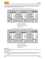
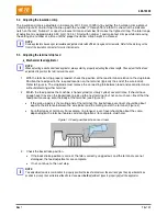
c. Using the backstroke adjustment knob (Figure 3), position the feed pawl to the proper back
position, typically the end of the wire barrel (Figure 13). If the end cap is in place, use a 3-mm
hex wrench or small screwdriver to reach through the end cap to rotate the feed adjustment
knob. The adjustments are in 0.08-mm [.003-in.] increments or 30 degrees and can be felt as
clicks.
If the pick-up point is the mating end of the terminal, the backstroke over-travel should be
about equal to the distance between the wire barrel and the mating end of the terminal
(Figure 3).
For other types of terminals (for example, ring tongue), over-travel should be about the
same, depending on the terminal features and configurations (for example, stud hole).
NOTE
To facilitate adjustments with certain machines or applications, the feed adjustments can also be made with the air pressure
removed. This allows more tactile feel of the detents. You must move the feed forward and back manually to check feed
positions. The air feed housing marking (shown in Figure 3) indicates the maximum backstroke travel of the feed arm. Verify
the feed forward and back positions after restoring air pressure.
d. Jog the machine to top-dead-center. The feed moves the next terminal over the anvil.
e. Check position of the terminal over the anvil, noting whether the terminal feed-forward position
must be moved.
f.
Cycle the machine manually until the feed pawl shifts back. This releases the air pressure on
the feed adjustment, making the adjustment detent positions easier to feel.
g. Using the feed-forward adjustment knob, change the feed-forward position based on the
direction and amount noted in substep d. The adjustments are in 0.04-mm [.0016-in.]
increments or 15 degrees, and can be felt as clicks while rotating the knob.
Turning the knob clockwise moves the feed pawl away from the anvil.
Turning the knob counter-clockwise moves the feed pawl toward the anvil.
NOTE
Make sure that only the feed adjustment knob turns, not the entire shaft. You might have to hold the backstroke adjustment
knob stationary to prevent unintended backstroke adjustments (use a 3-mm wrench when the end cap is in place).


