background image

408-32027

4 of 11

Rev A

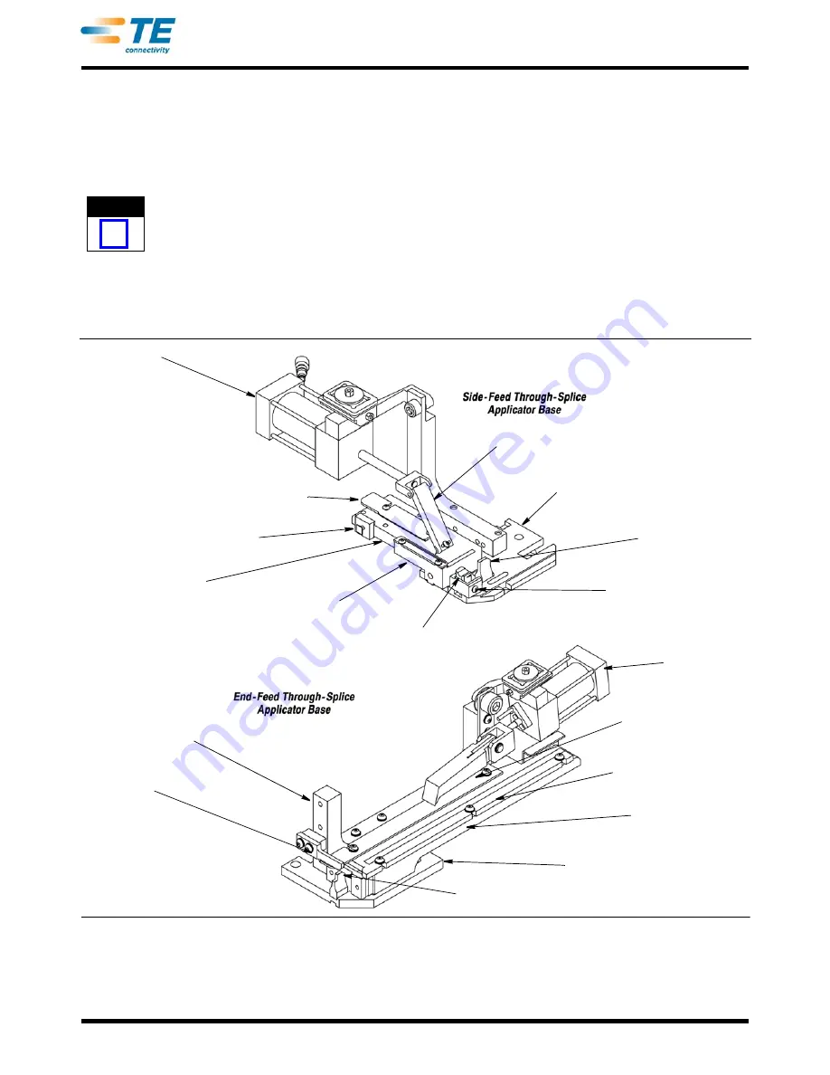
Terminal strip is fed into the applicator with the barrel 
(wire) end first, between the front (outer) and rear 
(inner) strip guides. It passes the stock drag, and the 
LEAD terminal is positioned over the anvil. The feed 
pawl feeds one terminal during each cycle of the 
machine. The terminals are fed by the action of the air 
cylinder that is controlled by a valve on the terminator.

NOTE

i

Some applicators have a solid metal hold-down 

that may require adjustment when changing the 

wire size and/or crimp height.

Terminals with dual-carrier strips require a shear 
depressor, spacer, and terminal holder. These parts 
are also attached to the tool holder assembly. The rear 
shear depressor pushes the rear floating shear down 

to cut the terminal from the rear carrier strip, and the 
terminal holder keeps the terminal from raising during 
the crimping and shearing process.

The anvil, the front shear holder, the rear shear holder 
(if used), the terminal support, and the strip guide 
adjustment block are mounted on the base plate, as 
well as the rear floating shear and rear shear holder.

The strip guide plate (Figure 5) is fastened to the strip 
guide adjustment block. The stock drag, the strip 
guide cover plate, and the front and rear strip guides 
are mounted on the strip guide plate.

The applicators used for the through-splice application 
are PRE-FEED Applicators. This means that the lead 
terminal is over the anvil when the machine is at rest.

Feed Cylinder

Front Strip Guide

Strip Guide Plate

Strip Guide 

Adjusting Block

Terminal Drag

Shear Retaining Screw

Anvil

Applicator 

Base Plate

Feed Finger

Feed Bracket

Stripper

Anvil

Applicator 

Base Plate

Strip Guide Plate

Front Strip Guide

Rear Strip Guide

Floating Shear

Feed Finger

Feed Cylinder

Figure 5

Содержание AMP 5k/40 CE

Страница 1: ...Terminators apply strip terminals to pre stripped wires Each applicator accepts the strip form of certain terminals which are identified on the applicator parts list and exploded view drawing Applicat...

Страница 2: ...d to allow access to both sides of the crimper for through splice type applications Refer to Figure 3 These guards work together with the applicator guards to protect the operator The left and right g...

Страница 3: ...inal from the strip The wire crimp is easily adjusted providing an array of different wire crimp sizes NOTE i All AMP 5K 40 CE Through Splice Terminators are equipped with a precision adjust feature T...

Страница 4: ...strip and the terminal holder keeps the terminal from raising during the crimping and shearing process The anvil the front shear holder the rear shear holder if used the terminal support and the strip...

Страница 5: ...r must be adjusted Refer to Paragraph 5 1 Crimp Height Adjustment If the lower portion has no movement then it is properly located side to side 2 Align the lower tooling to the upper tooling tool hold...

Страница 6: ...ard the stock drag and the open side up 6 Raise feed pawl and continue to feed terminal strip until LEAD terminal is over anvil and feed pawl engages hole in carrier strip 7 Turn terminal drag downwar...

Страница 7: ...justments as follows A Minor Crimp Height Adjustments Minor adjustments can be made using the manual adjust that is on the terminator The total adjustment range using this feature is approximately 018...

Страница 8: ...oward the rear of the anvil on the next feed stroke 10 Raise the terminal drag lift the feed finger and pull the terminal strip back and repeat steps 3 through 7 until the terminal is centered over th...

Страница 9: ...er strip but be sure the strip guides are parallel and that the terminal strip can move freely with a minimum of side clearance Retighten the screws NOTE i If feed pawl is not aligned with the front s...

Страница 10: ...the anvil is replaced the front shear and holder must be re aligned See Paragraph 5 6 A 6 Re align crimpers 6 2 Floating Shear Replacement Side Feed Through Splice Applicators Only NOTE i It is not n...

Страница 11: ...onnected before removing the applicator 1 With the power to the terminator off and the power cord disconnected open the terminator guard doors and remove the applicator as described in Paragraph 3 2 N...

Отзывы: