1.7 CONFIGURING THE IEEE INTERFACE
1.7.1 SETTING THE POWER SUPPLY AND IEEE SELECT SWITCH
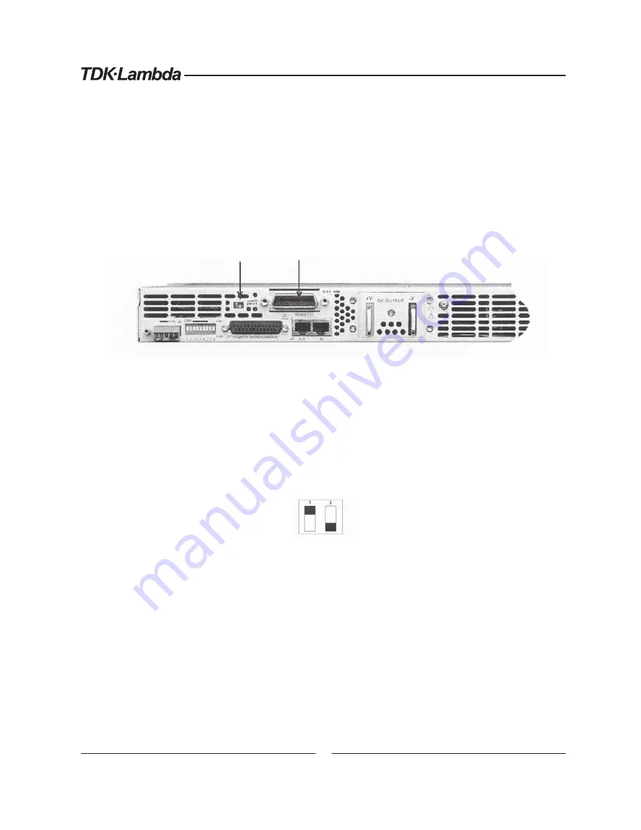
Power supply setting – set rear panel DIP switch (SW1) all contact to Down position.
The interface contains a two position DIP switch that is accessible from the rear of the
Power Supply and located next to the IEEE cable connector. Switch 2, located to the right
of Switch1, is not used. Refer to Figure 2 for location of the IEEE connector and the IEEE
select switch at the rear panel of the supply.
Figure 2.
IEEE Connector and IEEE Select Switch Location
Placing Switch 1 in the ON Position, up, will activate this interface and deactivate the
Power Supply’s Serial I/O capability. Placing Switch 1 in the OFF Position, down, will
deactivate this interface and activate the Power Supply’s Serial (RS232 or RS485) I/O
capability.
The position of Switch 1 may be changed at any time; but the new setting will not take
affect until the power is switched off and on.
UP
Down
Figure 3.
IEEE Select Switch
1.7.2 CONFIGURING THE IEEE CONTROLLER
A typical IEEE controller is a personal computer with an IEEE interface card. Each card
YHQGRUVXSSOLHVLWVRZQFRQ¿JXUDWLRQLQVWUXFWLRQVDQGLQWHUIDFHVRIWZDUH
(DFKWLPHWKHVRIWZDUHLVH[HFXWHGWKHFRQWUROOHUPXVWEHFRQ¿JXUHGDVIROORZV
Controller Address = 0. This is factory default for all controllers.
EOI Flag = TRUE. The “End or Identify” is a control line in the IEEE cable that is
asserted when the last character of a message string is sent. It is required for this
interface.
EOS Flag = FALSE: The “End of String”, used in some instruments to indicate the
last character of a message, is not supported by this interface.
IEEE select
switch
IEEE 488
connector
Содержание Genesys Series
Страница 1: ...6 3 3 0XOWL URS QWHUIDFH 2SWLRQ...
Страница 2: ...USER MANUAL FOR IEEE PROGRAMMING INTERFACE FOR GENESYSTM POWER SUPPLIES 5HY...
Страница 3: ...7KLV SDJH LQWHQWLRQDO OHIW EODQN...
Страница 40: ...NOTES...
Страница 41: ...NOTES...


