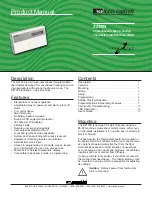
R
2800 LAURA LANE • MIDDLETON, WI 53562 • (800) 288-9383 • FAX (608) 836-9044 • www.tcsbasys.com
6
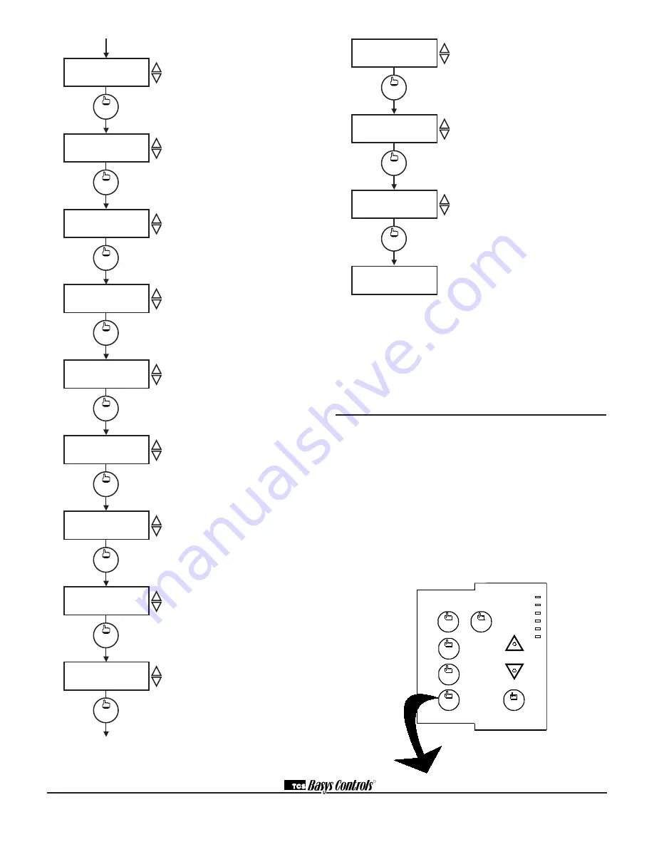
Outdoor Air Sensor Function Screen.
Choose whether or not you are using an
outdoor air sensor function. To monitor
only, select NO. See setup instructions
for dipswitch settings which must also
be set.
Cooling Lockout Screen.
Enter an
outdoor air cooling lockout temperature.
This screen will not appear if the outdoor
air sensor function is disabled.
Heating Lockout Screen.
Enter an
outdoor air heating lockout temperature.
This screen will not appear if the outdoor
air sensor function is disabled.
DI1 Choice Screen.
Choose DI1 as
FAN PROVING or a MONITOR point.
Select MONITOR if unused.
DI2 Choice Screen.
Choose DI2
as SERVICE, or MONITOR. Select
MONITOR if unused.
DI2 Shift Screen.
Enter the setpoint
shift value. This screen will only appear
if DI2 is set to MONITOR.
DI3 Choice Screen.
Choose FILTER
SERVICE, EXTernal OVERRIDE, or
EXTernal TIME CLOCK. Select EXTernal
OVERRIDE if unused.
Delay On Powerup Screen.
Enter a
value in seconds, such that when the unit
is powered up, all outputs are delayed for
this time period before they are allowed
to close.
Smart Recovery Screen.
Choose
whether or not smart recovery will be
used.
Note: Smart Recovery is not
available when DI3 is used as EXTernal
TIME CLOCK.
HEAT PUMP MODE CONVERSION TABLE
• Cool 1 Becomes Compressor
• Heat 1 Becomes Reversing Value
• Power up start up screen still displays “SZ1009”
• Everything else, not mentioned here, remains same as if it
is in conventional mode
Setting Clock & Schedule
The SZ1009 clock and schedule may be set through the
keypad and display, or with a PC. For more information
on programming through the PC, consult your TCS soft-
ware manual.
SETTING CLOCK & SCHEDULE
THROUGH THE KEYPAD
To access the clock and schedule screens, press the
clock setup button. To make changes, use the warmer
and cooler keys. For screens that have more than one
field to set, use the override key to move to the next
field. Access may be locked out with dipswitches, or an
access code may be required.
MON
72F
12:00 AM
SET DATE:
11-19-01
3.
1.
clock
setup
ENTER ACCESS
SET TIME & DAY:
MON
12:00 AM
2.
000
CODE
fan
Occupied
Heating
Cooling
Fan
Service
Program/
COOLER
WARMER
Data
switch
service
status
system
switch
program
setup
clock
setup
override
override
override
11-19-01
clock
setup
clock
setup
clock
setup
program
setup
DELAY ON POWERUP
010 SECONDS
36.
program
setup
ENABLE SMART
RECOVERY? NO
37.
program
setup
DI3 USED FOR:
FILTER SERVICE
35.
program
setup
REQUIRE CODE FOR
PROGRAMMING? YES
38.
program
setup
REQUIRE CODE FOR
CLOCK/SCHED? YES
39.
program
setup
SET ACCESS
CODE: 248
40.
MON.
12:00 AM 72F
program
setup
ENABLE OUTDOOR
AIR SENSOR? NO
29.
program
setup
SET DI2 SETPOINT
SHIFT:
00F
34.
program
setup
COOLING LOCKOUT
TEMP:
60F
30.
program
setup
DI1 USED FOR:
MONITOR
32.
program
setup
DI2 USED FOR:
MONITOR
33.
program
setup
HEAT LOCKOUT
TEMP:
70F
31.
Programming Access Screen.
Choose
whether or not a code will be required to
enter programming setup. A dipswitch
option to lock out access altogether is
also available.
Clock and Schedule Access Screen.
Choose whether or not a code will be
required to enter clock and schedule
setup. A dipswitch option to lock out
access altogether is also available.
Access Code Screen.
Enter a second-
ary access (0 to 255) code that will be
used to enter the programming and/or
clock and schedule setups if access code
has been required in the last two steps.
This code can be given to your customer
and can be changed later. The primary
code is 248, it always works and cannot
be changed.
Main Monitoring Screen.


