


Section 7.0 HMI Introduction
HGA IOM
84
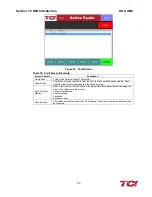
Table 26: Line/Load Status Screen Elements
Screen Element
Description
Volts Display
Displays the current utility phase to phase line Voltage in Volts RMS.
Current Display
Displays the current line/load phase current in Amps RMS.
Note:
The displayed current is affected by the CT Ratio configuration on the
“Setup” page.
Power Display
The 3-phase real power (P) of the line/load in kW.
Apparent Power Display The 3-phase apparent power (S) of the line/load in kVA.
Power Factor Display
Displays current line/load power factor. 1.00 indicates unity power factor. A
negative power factor indicates lagging power factor.
I THD Display
Displays the Total Harmonic Distortion of the utility Line/Load current as a
percentage
Note
: If secondary CT current is less than 1A, THID and THID Ref will be
unavailable
V THD Display
Displays the Total Harmonic Distortion of the utility line Voltage as a percentage.
I THD Ref Display
Displays the reference Total Harmonic Distortion of the utility Line current in a
percentage. This THD display is the uncorrected THD of the Line taken when the
HarmonicGuard
®
Active filter was not running.
Note:
For load side configured units, I THD Reference and I TDD displays are not
available
Note:
If secondary CT current is less than 1A, THID and THID Ref will be
unavailable
I TDD Display
Displays the Total Demand Distortion of the utility. By default, this is calculated
based on CT Ratio, but can be adjusted by entering the system Full Load Amps
(FLA) on the “Tech Setup” screen. See the “Tech Setup Screen” section below
Run/Stop Button
Runs and stops the HarmonicGuard
®
Active filter.
Back Button
Returns user to the main Status Screen.
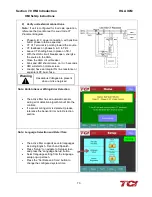
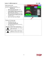
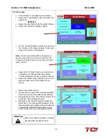
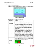
Waveform Plot Sub-Screens
The HMI display supports capture and display of real time system Voltage and current data. 3-
phase waveform data can be viewed for Line Voltage, Line/Load Current, and Converter
Corrective Current.
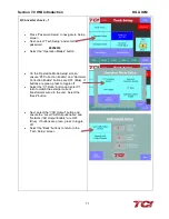
The waveform screens contain a zoom feature, which supports three magnitude scales: 1X, 2X
and 4X (see
Figure 42). The Refresh button on the waveform screens will update the plot with
new data from the HarmonicGuard
®
Active filter converter.
Содержание HGA HarmonicGuard Series
Страница 26: ...Section 4 0 Pre installation Planning HGA IOM 19 Figure 3 Altitude and Ambient Temperature Derating ...
Страница 40: ...Section 5 0 Installation Guidelines HGA IOM 33 Figure 11 HGA 480 V Two Unit Parallel Connection Diagram ...
Страница 42: ...Section 5 0 Installation Guidelines HGA IOM 35 Figure 12 HGA 480 V Three Wide Parallel Unit Connection Diagram ...
Страница 47: ...Section 5 0 Installation Guidelines HGA IOM 40 Figure 16 HGA 480 V Main Tie Main Connection Diagram ...
Страница 48: ...Section 5 0 Installation Guidelines HGA IOM 41 Figure 17 Current Transformer Diagram Round ...
Страница 49: ...Section 5 0 Installation Guidelines HGA IOM 42 Figure 18 Current Transformer Diagram Rectangular ...
Страница 76: ...Section 7 0 HMI Introduction HGA IOM 69 HMI Installation Diagram ...
Страница 138: ...Section 13 0 Appendix D DeviceNet Gateway Option HGA IOM 131 Figure 80 Ladder Diagram Observing HMI Status ...