


Section 7.0 HMI Introduction
HGA IOM
61
7.0 HMI Introduction
The Interface Module provides the user with a convenient way to monitor the operation of TCI’s
HarmonicGuard
®
Active filter and allows for the ability to adjust run-time set-points under
password control. This section describes how to install, operate, and maintain the Interface
Module.
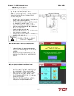
Overview
The Interface Module has three major components; the Interface PCB, the HMI Display and an
optional network Communications Gateway (see
The interface PCB contains a Chassis Communications Port that connects to the power converter
of the HarmonicGuard
®
Active filter. The interface PCB translates status and commands data
between the power converter controls and the HMI Display. The interface PCB also contains the
24V Relay I/O for basic status monitoring and run/stop control of the HarmonicGuard
®
Active
filter.
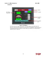
The HMI Display is a 6" color Touchscreen display containing a series of status screens that
provide the user with a convenient way to monitor the operation of the HarmonicGuard
®
Active
filter. The HMI display also contains an integrated ModbusRTU network connection for remote
monitoring of the HarmonicGuard
®
Active filter.
The optional network Communications Gateway can be connected to the integrated ModbusRTU
network connection in the HMI Display to translate the ModbusRTU protocol to an alternate
Fieldbus or Industrial Ethernet protocol such as Ethernet/IP.
Figure 30: Interface Module Components
Содержание HGA HarmonicGuard Series
Страница 26: ...Section 4 0 Pre installation Planning HGA IOM 19 Figure 3 Altitude and Ambient Temperature Derating ...
Страница 40: ...Section 5 0 Installation Guidelines HGA IOM 33 Figure 11 HGA 480 V Two Unit Parallel Connection Diagram ...
Страница 42: ...Section 5 0 Installation Guidelines HGA IOM 35 Figure 12 HGA 480 V Three Wide Parallel Unit Connection Diagram ...
Страница 47: ...Section 5 0 Installation Guidelines HGA IOM 40 Figure 16 HGA 480 V Main Tie Main Connection Diagram ...
Страница 48: ...Section 5 0 Installation Guidelines HGA IOM 41 Figure 17 Current Transformer Diagram Round ...
Страница 49: ...Section 5 0 Installation Guidelines HGA IOM 42 Figure 18 Current Transformer Diagram Rectangular ...
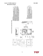
Страница 76: ...Section 7 0 HMI Introduction HGA IOM 69 HMI Installation Diagram ...
Страница 138: ...Section 13 0 Appendix D DeviceNet Gateway Option HGA IOM 131 Figure 80 Ladder Diagram Observing HMI Status ...