


Section 7.0 HMI Introduction
HGA IOM
97
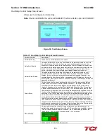
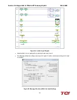
Auto Start Setup Sub-Screen
Allows user to configure the parameters necessary to use the Auto-Start option.
Note:
If button is GREEN, the option is ENABLED. If button is BLUE, option is DISABLED.
Figure 54: Auto Start Setup Screen
Table 38: Auto-Start Setup Screen Elements
Screen Element
Description
Auto-Start Enable
This option will set the converter to start automatically after a programmed delay
after power is applied or after a fault occurs. This option is on by default.
Select number of faults
Allows user to select number of faults allowed to occur before auto start option is
disabled.
Select time frequency
Allows user to select the time allowed between faults before auto start option is
disabled.
Disable Auto-Start Limit
The disable auto start limit button will disable the frequency limit or the number of
allowed unit auto-starts after a fault is detected.
Start Delay
The start delay is the time in seconds the active filter will wait after a power up or
after a fault before auto starting the harmonic and/or power factor correction, if the
auto start feature is enabled.
Fault Reset Delay
The fault reset delay is the time in seconds the active filter will wait after a fault is
detected prior to attempting to auto-clear the fault and restart harmonic and/or
power factor correction if the auto-start feature is enabled.
Back
Takes user back to the Tech Setup screen.
Содержание HGA HarmonicGuard Series
Страница 26: ...Section 4 0 Pre installation Planning HGA IOM 19 Figure 3 Altitude and Ambient Temperature Derating ...
Страница 40: ...Section 5 0 Installation Guidelines HGA IOM 33 Figure 11 HGA 480 V Two Unit Parallel Connection Diagram ...
Страница 42: ...Section 5 0 Installation Guidelines HGA IOM 35 Figure 12 HGA 480 V Three Wide Parallel Unit Connection Diagram ...
Страница 47: ...Section 5 0 Installation Guidelines HGA IOM 40 Figure 16 HGA 480 V Main Tie Main Connection Diagram ...
Страница 48: ...Section 5 0 Installation Guidelines HGA IOM 41 Figure 17 Current Transformer Diagram Round ...
Страница 49: ...Section 5 0 Installation Guidelines HGA IOM 42 Figure 18 Current Transformer Diagram Rectangular ...
Страница 76: ...Section 7 0 HMI Introduction HGA IOM 69 HMI Installation Diagram ...
Страница 138: ...Section 13 0 Appendix D DeviceNet Gateway Option HGA IOM 131 Figure 80 Ladder Diagram Observing HMI Status ...