Section 6.0 Filter Operation
HGA IOM
58
Figure 26: (480 V) 150, 300 Amp & (600 V) 110, 220 Amp Power Component Layout
Figure 27: (480 V) 200, 250, 500 Amp & (600 V) 150, 185, 370 Amp Power Component Layout
Output Terminal Bus Bars
Dual SCR Module
Dual SCR Module
Dual IGBT Module
Dual IGBT Module
Bus Bars over
Capacitors
Electrolytic Bus
Capacitors (6)
Positive
Terminal
Capacitor Bank
Negative
Terminal
Capacitor Bank
Содержание HGA HarmonicGuard Series
Страница 26: ...Section 4 0 Pre installation Planning HGA IOM 19 Figure 3 Altitude and Ambient Temperature Derating ...
Страница 40: ...Section 5 0 Installation Guidelines HGA IOM 33 Figure 11 HGA 480 V Two Unit Parallel Connection Diagram ...
Страница 42: ...Section 5 0 Installation Guidelines HGA IOM 35 Figure 12 HGA 480 V Three Wide Parallel Unit Connection Diagram ...
Страница 47: ...Section 5 0 Installation Guidelines HGA IOM 40 Figure 16 HGA 480 V Main Tie Main Connection Diagram ...
Страница 48: ...Section 5 0 Installation Guidelines HGA IOM 41 Figure 17 Current Transformer Diagram Round ...
Страница 49: ...Section 5 0 Installation Guidelines HGA IOM 42 Figure 18 Current Transformer Diagram Rectangular ...
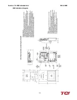
Страница 76: ...Section 7 0 HMI Introduction HGA IOM 69 HMI Installation Diagram ...
Страница 138: ...Section 13 0 Appendix D DeviceNet Gateway Option HGA IOM 131 Figure 80 Ladder Diagram Observing HMI Status ...


