


Section 7.0 HMI Introduction
HGA IOM
74
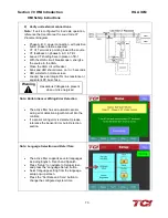
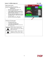
6) Running Converter
Press “Setup” to navigate to the setup screen
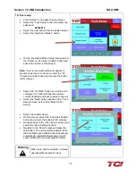
Select the “Tech Setup” button and enter the password:
08252014
•
Select the “Next” button from the splash screen
•
Select the “Operation Modes” button
•
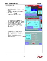
On the “Operation Mode Setup” screen ensure “PF
Correction Enable” and “Harmonic Correction Enable”
buttons are OFF (Blue). If buttons are green, press to
toggle off TODO and VAR output off.
•
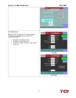
Select the “VAR Output” button and ensure the “Local
VAR Output Enable” and “Network VAR Output Enable”
are OFF (Blue). Select the “Back” buttons to go back to
“Tech Setup” screen
•
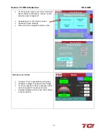
Select the “Home” button from navigation bar
•
Select the “Run” button to start unit operation
7) Remove CT shorting bars
•
Press “Stop” to turn off unit
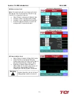
•
Disconnect power from cabinet
•
Turn off the built-in door breaker AND
•
Turn off the upstream feeder breaker
•
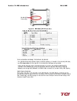
Open the cabinet door and remove shorting bars from
CTs connected to TB-1
Warning
Lethal Voltages may be present.
Wait 5 minutes for DC bus Voltage to
drop to safe levels.
Warning
Check for Voltage in cabinet with a
DMM before working inside cabinet.
Содержание HGA HarmonicGuard Series
Страница 26: ...Section 4 0 Pre installation Planning HGA IOM 19 Figure 3 Altitude and Ambient Temperature Derating ...
Страница 40: ...Section 5 0 Installation Guidelines HGA IOM 33 Figure 11 HGA 480 V Two Unit Parallel Connection Diagram ...
Страница 42: ...Section 5 0 Installation Guidelines HGA IOM 35 Figure 12 HGA 480 V Three Wide Parallel Unit Connection Diagram ...
Страница 47: ...Section 5 0 Installation Guidelines HGA IOM 40 Figure 16 HGA 480 V Main Tie Main Connection Diagram ...
Страница 48: ...Section 5 0 Installation Guidelines HGA IOM 41 Figure 17 Current Transformer Diagram Round ...
Страница 49: ...Section 5 0 Installation Guidelines HGA IOM 42 Figure 18 Current Transformer Diagram Rectangular ...
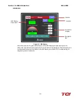
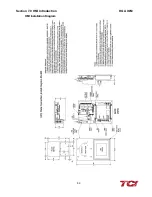
Страница 76: ...Section 7 0 HMI Introduction HGA IOM 69 HMI Installation Diagram ...
Страница 138: ...Section 13 0 Appendix D DeviceNet Gateway Option HGA IOM 131 Figure 80 Ladder Diagram Observing HMI Status ...