Section 6.0 Filter Operation
HGA IOM
54
the same with wires in positions 3 & 4. Apply power for proper power-up; if it doesn’t proceed
to #3.
3.
Reverse just one set of CT leads at a time, first 1 & 2; verify power-up. If it doesn’t, work
put wires 1 & 2 back and try the same with wires 3 & 4. Apply power for proper power-up;
if it doesn’t, replace all wiring to its original positions, and proceed to #4.
4.
There is a possibility that the phasing of the CT L1 and L3 are incorrect. To test this
theory, swap the two wires on TB-1 positions 1 & 2 with the two wires in positions 3 & 4.
Apply power for proper power-up; if it doesn’t repeat steps 2 and 3.
5.
If the HGA doesn’t indicate a run status after completion of steps 1 through 4, contact TCI
technical support for further assistance.
System Failure
The Digital Signal Processor is continually monitoring the performance and fault status of the
filter. It will shut down the converter section if the processor should sense a fault. The filter is also
equipped with a circuit breaker providing a second layer of over current protecting for the
converter section. The circuit breaker can also serve as a means of electrical isolation from the
system power grid. It is recommended by TCI that all power to the HarmonicGuard
®
Active filter
be disconnected. If you elect to service the HGA by using the circuit breaker to isolate the
converter section, please take special note of the following warnings:
Warning
Many electronic components located within the filter are sensitive to static electricity. Voltages
imperceptible to human touch can reduce the life, and affect performance, or destroy sensitive
electronic devices. Use proper electrostatic discharge (ESD) procedures when servicing the
filter and its circuit boards.
Warning
Only qualified electricians should carry out all electrical installation and maintenance work on
the HGA.
Disconnect all sources of power to the HGA and connected equipment before working on the
equipment. Do not attempt any work on a powered HGA.
This HGA unit contains high Voltages and capacitors. Wait at least five minutes after
disconnecting power from the filter before you attempt to service the conditioner. Check for
zero Voltage between all terminals on the capacitors. Also, check for zero Voltage between all
phases of the input and output lines. All maintenance and troubleshooting must be done by a
qualified electrician. Failure to follow standard safety procedures may result in death or serious
injury.
Unless an external disconnect means has been provided everything ahead of the
filter circuit breaker, including the reactors, will still be energized.
Required Equipment
•
AC Voltmeter and ammeter or multimeter designed for true RMS measurements in a harmonic
rich circuit and suitable for the rated current and Voltage marked on the nameplate. The meter
should have 1000 Volt minimum isolation.
•
Clamp-on current probe suitable for the rated current and Voltage marked on the
nameplate.
•
Clip-on Voltage probes suitable for the rated Voltage marked on the nameplate.
Select probes that can be securely clipped on to the test points without shorting
between points or falling off.
Note
: When disconnecting wires from components and terminations, mark the wires to
correspond to their component and terminal connection. Extreme care should be taken when
removing the fast-on terminals from the circuit board. Excessive force will result in damaging the
interface board and require the converter to be repaired by TCI authorized personnel only.
Содержание HGA HarmonicGuard Series
Страница 26: ...Section 4 0 Pre installation Planning HGA IOM 19 Figure 3 Altitude and Ambient Temperature Derating ...
Страница 40: ...Section 5 0 Installation Guidelines HGA IOM 33 Figure 11 HGA 480 V Two Unit Parallel Connection Diagram ...
Страница 42: ...Section 5 0 Installation Guidelines HGA IOM 35 Figure 12 HGA 480 V Three Wide Parallel Unit Connection Diagram ...
Страница 47: ...Section 5 0 Installation Guidelines HGA IOM 40 Figure 16 HGA 480 V Main Tie Main Connection Diagram ...
Страница 48: ...Section 5 0 Installation Guidelines HGA IOM 41 Figure 17 Current Transformer Diagram Round ...
Страница 49: ...Section 5 0 Installation Guidelines HGA IOM 42 Figure 18 Current Transformer Diagram Rectangular ...
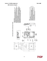
Страница 76: ...Section 7 0 HMI Introduction HGA IOM 69 HMI Installation Diagram ...
Страница 138: ...Section 13 0 Appendix D DeviceNet Gateway Option HGA IOM 131 Figure 80 Ladder Diagram Observing HMI Status ...


