background image


TBS Installation Manual 


3D FLASH+


TBS 3D FLASH+ Mounting and Installation Guideline    

    TBS-061    

    Rev 11-2023


page 2 of 17


Content 


Chapter 

Page 

1


Introduction ...................................................................................................................................... 3


2


Legal and Safety Instructions ............................................................................................................ 4


3


Mounting and Installation ................................................................................................................. 5


3.1


Recommended Mounting Information ................................................................................................ 5


3.2


Prepare the Unit for Installation .......................................................................................................... 5


3.3


Choose the Installation Type............................................................................................................... 6


3.4


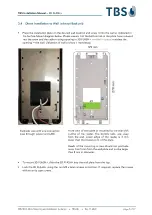
Direct Installation to Wall (without Backunit) ...................................................................................... 7


3.5


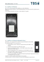
Installation with Backunit .................................................................................................................... 8


3.6


Installation with Fingerprint Recognition Sensor ................................................................................ 8


4


Power and Signal Wiring ................................................................................................................... 9


4.1


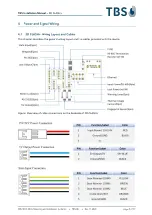
3D FLASH+ Wiring Layout and Cables ............................................................................................... 9


4.2


General Wiring Requirements ........................................................................................................... 11


4.3


Power Supply Wiring Recommendations .......................................................................................... 12


4.4


Ethernet Connection ......................................................................................................................... 12


4.5


Integrated Relay ................................................................................................................................ 12


4.6


Connecting TBS Controllers .............................................................................................................. 12


4.7


Connecting Third Party Controllers .................................................................................................. 13


4.7.1


RS485 Serial Interface .............................................................................................................. 13


4.7.2


RS232 Serial Interface .............................................................................................................. 13


4.7.3


Wiegand Connection ............................................................................................................... 13


5


Appendix ........................................................................................................................................ 14


5.1


Maintenance...................................................................................................................................... 14


5.2


Trouble Shooting .............................................................................................................................. 14


5.3


TBS port assignments ....................................................................................................................... 16


5.4


References to other TBS documents ................................................................................................ 17


Содержание 3D FLASH+

Страница 1: ...ocument TBS 061 NOTE The latest version of this document always available at https cloud1 tbs biometrics com index php s TWldCHnZtkRn0LV Release Author Comment July 15 2023 AG First version Nov 01 202...

Страница 2: ...7 3 5 Installation with Backunit 8 3 6 Installation with Fingerprint Recognition Sensor 8 4 Power and Signal Wiring 9 4 1 3D FLASH Wiring Layout and Cables 9 4 2 General Wiring Requirements 11 4 3 Pow...

Страница 3: ...figuration options on the market This document describes the mounting and installation of the 3D FLASH As an optional add on a Fingerprint sensor can be attached to the base reader The installation of...

Страница 4: ...als or attending TBS trainings webinars When not otherwise stated the following safety instructions apply Installation and servicing of our appliances must be carried out when disconnected from the po...

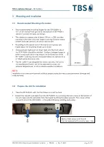
Страница 5: ...d Sunlight halogen lamps or other strong illumination may reduce the performance of the 3D FLASH and may result in increased failure to capture rates or failed authentication events The 3D FLASH was d...

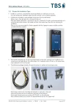
Страница 6: ...en protrude further from the wall allowing for ventilation This version is recommended if a further upgrade with the fingerprint sensor module could be considered by the customer The metallic wall pla...

Страница 7: ...atches the opening in the wall Utilization of wall anchors is mandatory To mount 3D FLASH slide the 3D FLASH into the wall plate from the top Lock the 3D FLASH using the two M3 x 6mm screws on bottom...

Страница 8: ...steps for a new installation are 1 Install the FRS to the wall The backunit supplied with the 3D FLASH is not required 2 Install the metal wall plate on the FRS with 6 screws 3 Connect the USB plug f...

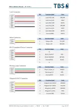
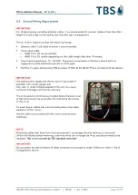
Страница 9: ...ation Guideline TBS 061 Rev 11 2023 page 9 of 17 4 Power and Signal Wiring 4 1 3D FLASH Wiring Layout and Cables This chapter describes the general wiring layout and the cables provided with the devic...

Страница 10: ...TBS Installation Manual 3D FLASH TBS 3D FLASH Mounting and Installation Guideline TBS 061 Rev 11 2023 page 10 of 17...

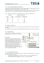
Страница 11: ...des 15 VDC 4A 60 W PSU is included with the device IMPORTANT Use stable power supply and shorter power input cable if possible with correct gauge wire Any over or under voltage applied to this unit ma...

Страница 12: ...ing peripheral devices the cable should be of Cat5 or higher it does not need to be crossed 4 5 Integrated Relay Depending on the 3D FLASH input voltage set Switch 4 position to choose from 12 or 24 V...

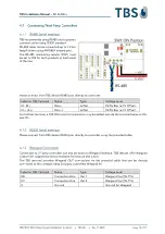
Страница 13: ...V Offset IO A Data In Out 0V 5V Bias 7 V Offset For farthest terminal a 120 Ohm resistor termination may be added outside the terminal between IO and IO 4 7 2 RS232 Serial Interface Please connect fro...

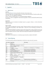
Страница 14: ...ts with dust or where oily substances are handled or other extraordinary environmental factors are present the sensor surfaces need to be checked and cleaned with increased frequency Replacement Parts...

Страница 15: ...eral problem with external verification initiated from 3rd party software 441 Empty token comes from external device 500 General logic error 501 User presented card in smartmode and he does not have i...

Страница 16: ...tion channel BME installer sets required firewall settings by default Yes No Biometric Client Service PC BME channel 1 8808 HTTPS communication channel to BME server and Device Control Center DCC No Y...

Страница 17: ...artner Portal with full product documentations and access to latest firmware for terminals Access is restricted to registered TBS Partners TBS System Requirements Permanent link https cloud1 tbs biome...

Отзывы: