TBS Installation Manual
–
3D FLASH+
TBS 3D FLASH+ Mounting and Installation Guideline
•
TBS-061
•
Rev 11-2023
page 11 of 17
4.2
General Wiring Requirements
IMPORTANT:
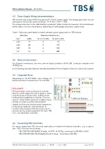
For all signal wiring, including ethernet cables, it is recommended to connect cables of less than 30m
length to avoid surge current spikes that may damage the equipment.
The 3D
FLASH+
requires at least the following wiring:
▪
Ethernet cable: Cat5 cable or better is recommended.
▪
Power input cable:
□
AWG 14 to 18: recommended
□
AWG 19 or 20: usable depending on the cable length (less than 10 meters)
▪
Power Input requirement: 15
–
24 VDC. The power consumption of the base device (with no
fingerprint module attached) amounts to 12 W peak.
▪
The Power supply delivered by TBS provides 15 VDC @ 4A (60 W; PSU is included with the device)
IMPORTANT:
Use stable power supply and shorter power input cable if
possible, with correct gauge wire.
Any over- or under-voltage applied to this unit may cause
permanent damage and void the warranty.
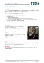
The on-board wire terminals are located below the back cover
of the terminal and are accessible after removing the screws
of this cover.
To insert power cables into wire terminals please strip cable
insulation off for ~5mm.
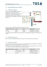
Use the cable set provided with the unit to connect serial
interfaces.
NOTE:
Removing cables with force from the wire terminal may damage the wire terminal or the board.
Unlock the latches before removing, otherwise wires can no longer be fixed, and board needs to be
replaced.
This is not covered by TBS standard warranty!
IMPORTANT:
Do not power the device before all cable connections are properly made. Otherwise, there is risk of
damaging the device.


