TBS Installation Manual
–
3D FLASH+
TBS 3D FLASH+ Mounting and Installation Guideline
•
TBS-061
•
Rev 11-2023
page 13 of 17
4.7
Connecting Third Party Controllers
4.7.1
RS485 Serial Interface
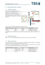
TBS recommends using RS485 and to protect
communication using OSDP standard.
RS-485 cable can be connected up to 1.2 km
length (when using AWG#24 twisted pair).
The RS-485 terminating resistor (SW1) must
be set to ON for both products at both ends
of the line.
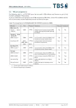
Please connect from TBS device RS485 port directly to controller:
Label on TBS Terminal
Name
Type
Voltage Level
IO- (B-)
Data -
In/Out
0V-5V Bias (
±
7 V Offset)
IO+ (A+)
Data +
In/Out
0V-5V Bias (
±
7 V Offset)
For farthest terminal, a 120-Ohm resistor termination may be added outside the terminal between IO+
and IO-.
4.7.2
RS232 Serial Interface
Please connect from TBS device RS232 port directly to controller using the provided cable.
4.7.3
Wiegand Connection
Connection to 3
rd
party controllers can also be done via Wiegand interface. TBS devices offer Wiegand
output lines supporting various standard formats (26 and 37bit).
The TBS terminal provides Wiegand OUT connections via the provided cable that can be directly
connected to the corresponding 3rd party controllers Wiegand IN.
Label on TBS Terminal
Name
Type
Voltage Level
D0
Connection Zero
Out 1
Wiegand Out (5V TTL)
D1
Connection One
Out 2
Wiegand Out (5V TTL)
G
Ground
Ground for Wiegand


