TBS Installation Manual
–
3D FLASH+
TBS 3D FLASH+ Mounting and Installation Guideline
•
TBS-061
•
Rev 11-2023
page 12 of 17
4.3
Power Supply Wiring Recommendations
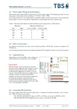
TBS recommends using a AWG16 gauge and 15-24 VDC power supply. The voltage specified is the one
measured on the product block connector: 15-24 VDC (-15% / +10%).
The voltage drop due to the cable shall be considered. Table 3 shows the maximum distance between
power supply and one unique device, depending on cable gauge and power supply rating.
Table 1: Maximum cable length in meters between power supply and one TBS terminal
Wire Size
Maximum distance [m]
mm
2
AWG
for 15 V ±10%
for 24 V ±10%
0.32
22
2
70
0.52
20
3
115
0.82
18
6
185
1.31
16
9
280
4.4
Ethernet Connection
For Ethernet connections, the wire terminal board provides a RJ45 LAN connector compliant with
IEEE802.3at.
For connecting peripheral devices the cable should be of Cat5 or higher (it does not need to be crossed).
4.5
Integrated Relay
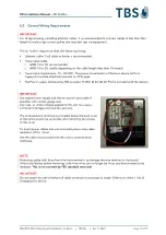
Depending on the 3D FLASH+ input voltage, set
Switch 4 position to choose from 12 or 24 VDC.
DISCLAIMER:
On-board relays must not be used to activate
security access equipment such as gates or doors
to grant access to secure areas, as they can be
accessed and bridged by an intruder. Only non-
security critical functionality such as lights may be
directly activated using the internal switch.
Instead, use the data communication capabilities
of the device (ethernet, serial interfaces) to
communicate to relays inside the secure area to
activate security access equipment. For such, TBS
offers two dedicated controllers.
4.6
Connecting TBS Controllers
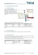
For various applications TBS Terminals need to be connected with external controllers, e.g. to open a
door. TBS offers two own solutions:
-
TBS CONTROLLER SMART (4 relays, 4x GPIN, 4x GPOut, connected via RS-485 or LAN)
-
TBS CONTROLLER LITE (RelayBoard with 2 relays, connected via RS-485)


