OPERATING PROCEDURES
6-9
Model 8756
Operating Procedures
6
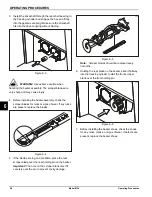
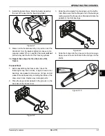
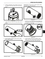
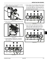
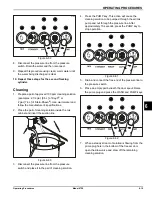
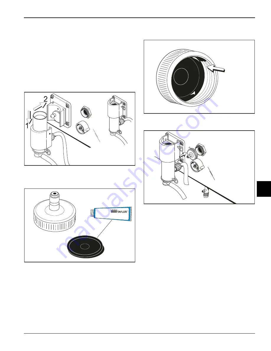
14. Align the drive hole in the piston to the ball crank of
the motor reducer. Simultaneously, align the locating
pin on the face plate.
Slide the pump collar upward into the grooves on the
side of the face plate and secure the air/mix pump in
place by slipping the keeper pin through the
crossholes of the pump collar.
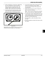
Important!
Alignment of the air/mix pump is
extremely important. Severe and costly damage may
occur when it is not properly aligned.
Figure 6-35
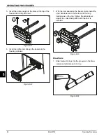
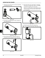
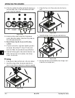
15. Lubricate both sides of the pressure switch
diaphragm.
Figure 6-36
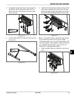
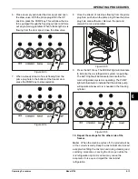
16. Place diaphragm into groove of the pressure switch
cap.
Figure 6-37
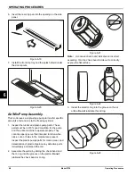
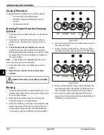
17. Screw the cap securely onto the housing.
Figure 6-38
Note:
Repeat these steps for other the side of freezer.
Sanitizing
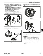
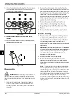
1. Prepare a pail of approved 100 ppm sanitizing
solution (examples: 2-1/2 gal. [9.5 L] of Kay-5
®
or
2 gal. [7.6 L] of Stera-Sheen
®
). Use warm water and
follow the manufacturer's specifications.
2. Place the pail of sanitizing solution inside the mix
cabinet.
15055
15056
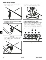
Apply the appropriate
Taylor approved food safe lubricant.
15057
15058
Содержание Horizon 8756
Страница 18: ...4 6 OPERATOR PARTS IDENTIFICATION Model 8756 Operator Parts Identification 4 Notes ...
Страница 22: ...5 4 USER INTERFACE Model 8756 User Interface 5 Notes ...
Страница 40: ...6 18 OPERATING PROCEDURES Model 8756 Operating Procedures 6 Notes ...
Страница 46: ...8 4 TROUBLESHOOTING GUIDE Model 8756 Troubleshooting Guide 8 Notes ...
Страница 48: ...9 2 PARTS REPLACEMENT SCHEDULE Model 8756 Parts Replacement Schedule 9 Notes ...
Страница 52: ...10 4 LIMITED WARRANTY ON EQUIPMENT Model 8756 Limited Warranty on Equipment 10 Notes ...
Страница 56: ...11 4 LIMITED WARRANTY ON PARTS Model 8756 Limited Warranty on Parts 11 Notes ...
Страница 57: ...Section 12 12 1 Model 8756 Wiring Diagrams 12 Wiring Diagrams 037807 33 4 15 2015 Taylor Company c Model 8756 ...
Страница 58: ...12 2 WIRING DIAGRAMS Model 8756 Wiring Diagrams 12 Notes ...

