51
Steering lock cum ignition switch
It is located on right hand side of
steering column. It has following
positions.
‘LOCK’ Position
Key can be inserted or removed in
this position only. Steering wheel gets
locked, only when key is removed.
‘ACC’ Position
Steering gets unlocked in this
position. Only accessories are ON.
‘ON’ Position
By turning the key to position ON, low
oil pressure lamp, battery charging
indicator lamp, parking brake
indicator lamp (if applied), fuel gauge
and temperature gauge are switched
on. Other electrical systems are
ready for operation. If none of the
above warning indicators /gauges are
working the chances are that the
fuse for engine and gauges is blown
off in which case engine will not
start.
‘START’ Position
Turn the key further clockwise to start
position to operate starter motor. This
is a spring return position.
As soon as the engine starts, release
ignition key so that the key can come
back to ON position and starter motor
disengages.
2.4 Switches, gauges & indicators
Know Your Vehicle
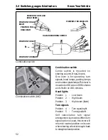
Steering lock cum ignition switch with
key (LHD)
Содержание LP 613 EURO-II
Страница 41: ...39 2 1 Vehicle identification KnowYourVehicle LP 613 CHASSIS WITH COWL 38 WB EURO II LHD ...
Страница 42: ...40 2 1 Vehicle identification KnowYourVehicle LPT 613 CHASSIS WITH CAB AND LOAD BODY 38 WB EURO II LHD ...
Страница 99: ...102 4 10 Brake system Maintenance AIR BRAKE SYSTEM WITH ABS IF FITTED ...
Страница 100: ...103 4 10 Brake system Maintenance SCHEMATIC LAYOUT OF DUAL CIRCUIT FULL AIR S CAM BRAKES WITH LCRV ...
Страница 141: ...147 6 Fuel Lubricants and Coolant 6 1 Fuel 149 6 2 Lubricants 150 6 3 Coolant 152 ...
Страница 165: ...173 4 15 Electricals Maintenance WIRING DIAGRAM LP LPT 613 EURO II Drg Part No 2641 5400 00 11 Sheet No 1 of 16 ...
Страница 166: ...174 4 15 Electricals Maintenance WIRING DIAGRAM LP LPT 613 EURO II Drg Part No 2641 5400 00 11 Sheet No 2 of 16 ...
Страница 167: ...175 4 15 Electricals Maintenance WIRING DIAGRAM LP LPT 613 EURO II Drg Part No 2641 5400 00 11 Sheet No 3 of 16 ...
Страница 168: ...176 4 15 Electricals Maintenance WIRING DIAGRAM LP LPT 613 EURO II Drg Part No 2641 5400 00 11 Sheet No 4 of 16 ...
Страница 169: ...177 4 15 Electricals Maintenance WIRING DIAGRAM LP LPT 613 EURO II Drg Part No 2641 5400 00 11 Sheet No 5 of 16 ...
Страница 170: ...178 4 15 Electricals Maintenance WIRING DIAGRAM LP LPT 613 EURO II Drg Part No 2641 5400 00 11 Sheet No 6 of 16 ...
Страница 171: ...179 4 15 Electricals Maintenance WIRING DIAGRAM LP LPT 613 EURO II Drg Part No 2641 5400 00 11 Sheet No 7 of 16 ...
Страница 172: ...180 4 15 Electricals Maintenance WIRING DIAGRAM LP LPT 613 EURO II Drg Part No 2641 5400 00 11 Sheet No 8 of 16 ...
Страница 173: ...181 4 15 Electricals Maintenance WIRING DIAGRAM LP LPT 613 EURO II Drg Part No 2641 5400 00 11 Sheet No 9 of 16 ...
Страница 174: ...182 4 15 Electricals Maintenance WIRING DIAGRAM LP LPT 613 EURO II Drg Part No 2641 5400 00 11 Sheet No 10 of 16 ...
Страница 175: ...183 4 15 Electricals Maintenance WIRING DIAGRAM LP LPT 613 EURO II Drg Part No 2641 5400 00 11 Sheet No 11 of 16 ...
Страница 176: ...184 4 15 Electricals Maintenance WIRING DIAGRAM LP LPT 613 EURO II Drg Part No 2641 5400 00 11 Sheet No 12 of 16 ...
Страница 177: ...185 4 15 Electricals Maintenance WIRING DIAGRAM LP LPT 613 EURO II Drg Part No 2641 5400 00 11 Sheet No 13 of 16 ...
Страница 178: ...186 4 15 Electricals Maintenance WIRING DIAGRAM LP LPT 613 EURO II Drg Part No 2641 5400 00 11 Sheet No 14 of 16 ...
Страница 179: ...187 4 15 Electricals Maintenance WIRING DIAGRAM LP LPT 613 EURO II Drg Part No 2641 5400 00 11 Sheet No 15 of 16 ...
Страница 180: ...188 4 15 Electricals Maintenance WIRING DIAGRAM LP LPT 613 EURO II Drg Part No 2641 5400 00 11 Sheet No 16 of 16 ...


