


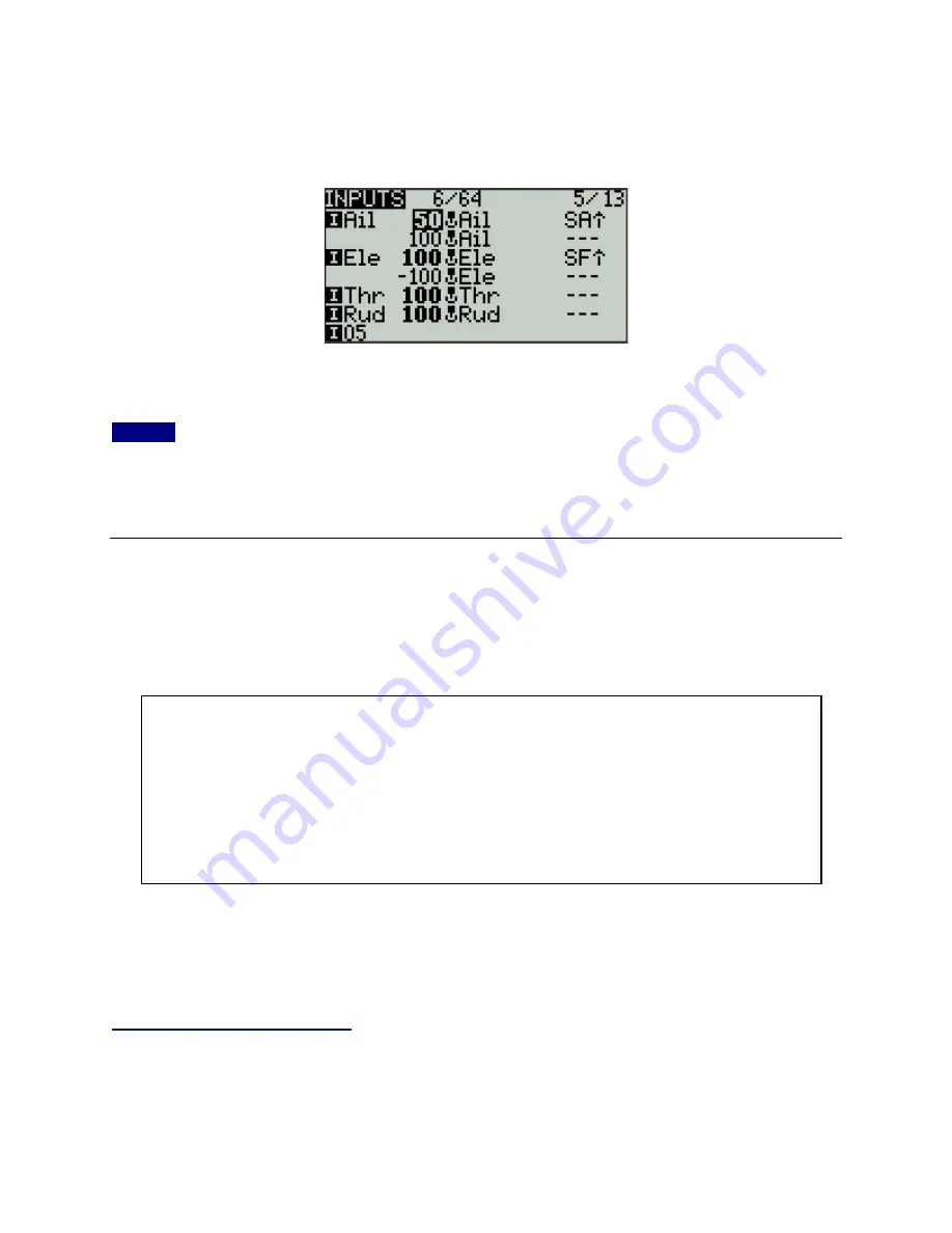
Your INPUTS screen now looks like this:
When Switch
SF
is up (SF
⇑
) the elevator response is normal, but when
SF
is not up the throttle
response is reversed. You can of course choose a different switch to suit your preferences.
NOTE:
Aircraft users program a different type of invert switch because this simple approach
does not invert the axis trim setting. Trims are important if you’re controlling servos, but robot
motor controllers seldom rely on trims to adjust their center position. This approach should work
just fine for your robot. If not, look up the aircraft version on the ‘net.
The OUTPUTS Screen -- Limiting and Reversing
I’ve arranged the topics in this guide to mirror the order of progression a robot builder might
follow in setting up a Taranis Q X7 for their use. At this point it would be helpful to follow a
position signal all the way thru the transmitter to better understand the ‘big picture’.
So, the
OUTPUTS
screen is the last stop before the signal is transmitted to the receiver. Any
adjustments made here will modify the output port assigned on the MIXER screen by adjusting
the magnitude and direction of the signal that will arrive at the receiver port.
Limiting Motion on a Servo
Suppose you have a servo powered 4-bar lifter in your antweight that’s controlled by the
‘Throttle’ stick axis on
CH3
. This particular mechanism does not require the full range of servo
motion to drive the lifter – the lifter is completely retracted at -75% of servo motion and is fully
A position signal is generated by a stick axis, switch, or knob.
That signal may be routed to the
INPUTS
screen for modification before being
passed to the mixer.
Signals coming into the
MIXER
screen may be combined with other before being
assigned to a receiver output port.
The
OUTPUTS
screen allows final modification to the direction and magnitude of
the combined signals from the mixer before they are transmitted to the receiver.