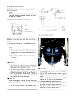
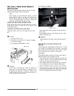
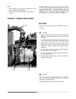
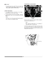
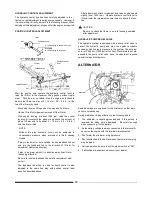
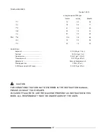


BOOSTER CONNECTION
In case the battery has run down making it impossible to start
the engine, the booster is used for starting the engine using
good battery of the other vehicle (12V specification vehicle) as
power source. Following procedure should be observed In such
case:
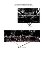
PROPER PROCEDURE FOR BOOSTER CONNECTION
CORRECT
CONNECTION
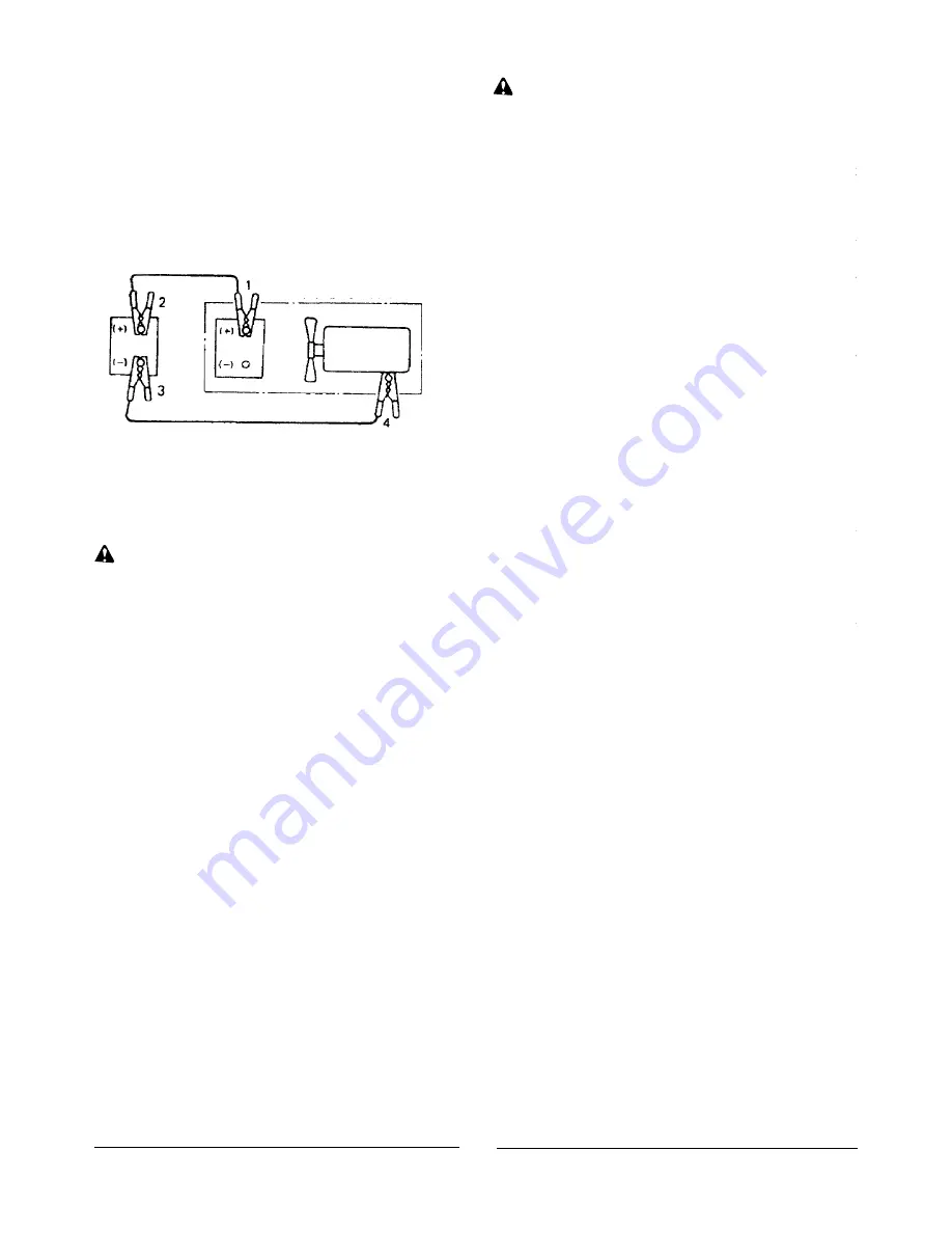
Troubled tractor
Engine
WARNING
Do not fail to perform in above order.
During the final connection, spark will be generated.
Therefore, connect the (-) clip to the engine block at as far
away point from the battery that is generating gas as possi-
ble.
Before connecting the cables, remove the electrolyte port
plugs where possible, because as long as such plugs have
been removed, the explosion will be smaller even if it may
catch fire resulting in smaller damage.
5.
Start the engine on the troubled vehicle.
If the engine is difficult to start, try to start it after starting the
engine of the normal vehicle.
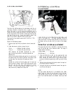
PROPER PROCEDURE FOR REMOVING BOOSTER
CABLES
Before connecting the booster, carefully check the followings to
see:
That the spring In the cable clip is normal.
That cable or clip is not broken or corroded.
CAUTION
1.
Select a booster cable with as large a capacity as possible.
It
must resist a 200A
current.
2.
Stop the engine of the vehicle (source side) which is in nor-
mal operation.
3.
Connect a clip of the booster cable (in red) to
(+)
terminal
of
the battery on the troubled vehicle and firmly connect anoth-
er clip to
(+)
terminal of the normal vehicle.
4.
Then connect a clip of another booster cable (in black) to
(-)
terminal of the normal vehicle and finally connect another
clip firmly to the engine block.
CORRECT
DISCONNECTION
After the engine is started, remove the booster cables in the
reversed procedure of above.
1.
First remove the
(-)
end clip from the engine block of
the
troubled vehicle, then remove another clip from the
(-)
terminal of the normal vehicle.
2.
Then remove a clip from
(+)
terminal of the normal
vehicle,
followed by removal of another clip from the
(+)
terminal of
the troubled vehicle.
34
Содержание VST 818
Страница 2: ......
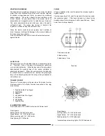
Страница 16: ...SECTION 2 EXTERNAL VIEW AND NOMENCLATURE OF EACH PART The above photos show TARAL VST 818 6 ...
Страница 35: ...25 ...
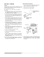
Страница 36: ...GREASING DIAGRAM Greasing Nipple Greasing Nipple Greasing Nipple 26 ...
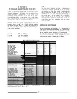
Страница 45: ...PROPER BATTERY MAINTENANCE AND TIPS FOR SAFETY 35 ...
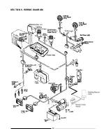
Страница 53: ...SECTION 8 WIRING DIAGRAM 43 ...
Страница 58: ......
Страница 59: ......