
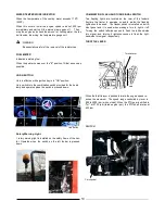
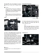
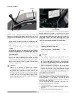
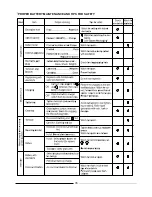
POSITION CONTROL
Stopper A
Stopper B
Position Control lever
Position control is provided for determining and holding the
position of an implement as desired by means of a lever.
To use
the position control, operate the control lever in the following
manner:
Pulling the lever backward will cause an implement to rise.
Pushing forward will cause an Implement to lower by its own
weight.
Placing the lever at certain position, causes implement to
move to and stop at the height corresponding to the position
of
the lever.
For holding the height of the Implement at certain position
constantly, use stopper
A
to fix the lever position, which will
make the lowered position of an implement to be maintained
at
the constant height.
Position control lever can also be operated to control depth
during driving. When an obstacle is encountered, the lifting
arms moves upward automatically and returns to its initial
position after the obstacle is passed.
This functions provides
easy use and operation without the need to change lever
adjustment during driving.
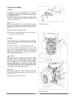
CAUTION
Stopper
B
is
provided
to
prevent
the
hydraulic
safety
valve from being actuated. Be sure not to move It for
any
purpose other than hydraulic power take off. For
returning
the displaced stopper B to its original position,
first oper-
ate the position control lever in upward
direction, then
from the position where actuating sound
of the safety
valve starts, slide the stopper B downward by
5 to 8 mm
and tighten it there.
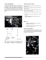
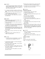
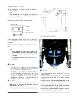
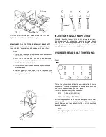
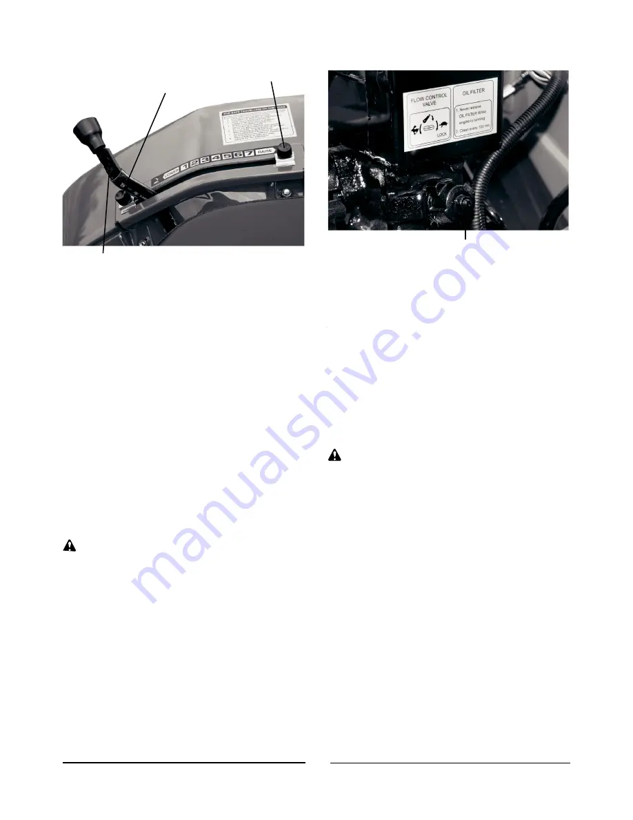
Flow Control Knob
The tractor provides the flow control knob which controls the
lowering speed of the implement. It is located in front of the
hydraulic case under seat. When the knob is turned clockwise,
the lowering speed slows down, and when further turned, the
control valve is closed.
As a result, the implement will be held
in its position and will not move downward any further.
Turning
the knob counterclockwise increases the lowering speed.
NOTE
Adjust the lowering speed according to the type of an
implement and operating conditions.
Rotary
tiller
operation
Lowering
speed
. . . . .Slow
Plow
operation
Lowering
speed
. . . .Fast
WARNING
1.
For travelling on the road, be sure to turn the flow control
knob all the way clockwise and lock it there.
2.
During tine replacement, grass or straw removal of rotary
tiller, or during inspection of implement for the safety, place
the lift arms in upward position, shut down the engine and
be sure to lock the flow control lever.
3.
When an implemented is mounted on the 3-point linkage
levers, do not stand or allow others to stand between the
implement and the tractor. If there is an adjustment, removal
or mounting is required, lower the implement slowly to the
ground, apply the parking brake and proceed afterwards.
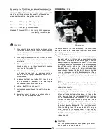
RECOMMENDED IMPLEMENTS
There are a number of implements available which match the
3-point linkage system of the tractor. When mounting and using
these implements, it is very important you load the tractor
according to the permitted axle loads, otherwise unexpected
failures or accidents may occur.
For main implements that can be mounted to the tractor, use
the recommended implements listed below:
1.
3 or 2 disc 8" plough.
2.
4 row and 6 row, 16 and 24 blades 850mm and 1000mm
rotary tiller.
3.
200lt mounted pesticide application equipment.
20
Содержание VST 818
Страница 2: ......
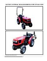
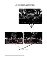
Страница 16: ...SECTION 2 EXTERNAL VIEW AND NOMENCLATURE OF EACH PART The above photos show TARAL VST 818 6 ...
Страница 35: ...25 ...
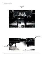
Страница 36: ...GREASING DIAGRAM Greasing Nipple Greasing Nipple Greasing Nipple 26 ...
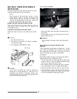
Страница 45: ...PROPER BATTERY MAINTENANCE AND TIPS FOR SAFETY 35 ...
Страница 53: ...SECTION 8 WIRING DIAGRAM 43 ...
Страница 58: ......
Страница 59: ......