Standalone DVR – Jupiter Series
73
6.2.3 Color
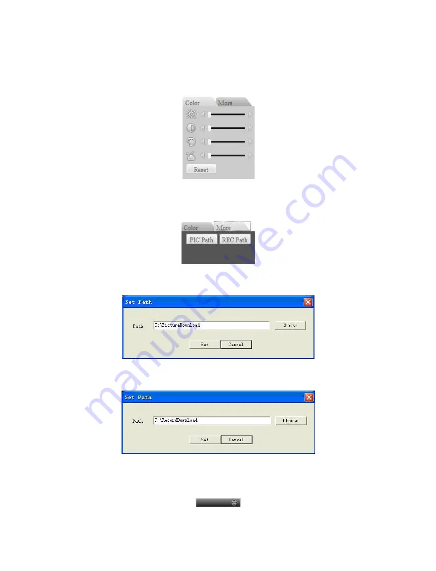
Click “Color” button in section 3, the interface is shown as Figure 6-14.
Here you can select one channel and then adjust its brightness, contrast, hue and saturation.
(Current channel border becomes green).
Or you can click default button to use system default setup.
Figure 6-14
6.2.4 Picture Path and Record Path
Click “More” button in Figure 6-14, you can see an interface is shown as in Figure 6-15.
Figure 6-15
Click “PIC Path” button, you can see an interface is shown as in Figure 6-16.
Figure 6-16
Click “REC Path” button, you can see an interface is shown as in Figure 6-17.
Figure 6-17
6.2.5 Menu Interface Switch
Put your cursor on the PTZ control bar until you see the following icon. See Figure 6-18.
Figure 6-18
Содержание Jupiter 30450711S
Страница 15: ...Standalone DVR Jupiter Series 15 2 6 Application Diagram...
Страница 29: ...Standalone DVR Jupiter Series 29 Figure 4 16 Figure 4 17 Figure 4 18...
Страница 33: ...Standalone DVR Jupiter Series 33 Figure 4 21 Figure 4 22 Figure 4 23 Figure 4 24...
Страница 87: ...Standalone DVR Jupiter Series 87 Figure 6 39 Figure 6 40 Figure 6 41 Figure 6 42...


