


⑤
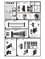
Setup of functions and beam alignment
Refer to Functions description for detailed explanation
of each option.
Supply power with cover off.
Set function options.
Location Functions
Function switches
TX / RX
Beam channel
(frequency)
1ch.
2ch.
3ch.
4ch.
TX only
Beam power
H
L
RX only
”Beep” alignment
tone
ON
OFF
Response time
adjustment
0.05sec. (standard)
0.3sec.
0.7sec.
Others
Alarm output
NO
NC
Environmental
output
NO
NC
Alarm memory
Auto-reset
Manual
Adjust optical angle
13
- Look through view finder on either side of the upper
transmitter optical unit and move until the receiver
unit is visible.
- Repeat the procedure for the lower optical unit, then
repeat on receiver.
13
A
- View Finder
13
B
- Horizontal fine adjustment screw
13
C
- Vertical adjustment screw
13
D
- Adjustment dial
Fine tuning
13
Initial beam alignment can be achieved by using the
alignment tone indicator.
- Attach the shading plates (located at the sides of
both TX / RX) to the lower optics of both TX and RX.
- Turn the receiver alignment tone switch to ON.
- Adjust the optics with the adjustment screws until
the highest tone is reached. (Note: There will be no
sound if the attenuation alignment tone LED lights
up.)
- Reverse the procedure, i.e. attach shading plates to
upper optics of T / R and repeat adjustment.
- After the adjustment, replace the shading plates in
the retaining areas of TX / RX.
- Turn the alignment tone indicator to OFF.
13
E
- Sensitivity attenuation LED (lights up when
beam reception is below minimum level)
13
F
- Alignment tone switch
13
G
- Monitor jack
Beam alignment using voltmeter
13
H
Precise alignment can be achieved by using a
voltmeter (10VDC). Connect the leads from the
voltmeter to the monitor jacks of the receiver. The
measurings for alignment are as follows.
13
H
- Voltmeter (10VDC)
Voltage reading
Alignment
2.7V or more
Best
2.0V to 2.7V
Good
2.0V or less
Poor, re-adjust
Attach cover
- Attach transmitter cover first.
- Confirm that receiver sensitivity attenuation LED
remains OFF. Place cover in position, but do not
secure. A ”beep” sound will occur after five seconds.
After this signal, secure the receiver cover with
screws.
Sensitivity allowance is automatically set when
the beep sound is initiated.
If the sound alignment switch is left ON
accidentally, the sound will cease when the
receiver cover is attached.
- If there is a continous ”beep” sound, detach the
receiver cover and re-adjust it, referring to the
auto-gain lock function.
Operation check
14
After installation, alignment and auto-gain set, test
operation by a walktest of the beam. Two methods
may be used:
Alarm LED only.
Alarm LED and sound check by means of the sound
alignment switch. If the sound alignment switch is
set to ”ON”, the sound will stop when the cover is
replaced but be effective for an audible operation
test for five minutes after the auto-gain is locked.
14
A
: Check by alarm LED
14
B
: Check by walk test mode
Functions description
Four channel frequency selection
15
The beam pairs may be set at various frequency
levels to avoid crosstalk between units which are
stacked, in-line, or other configurations that have the
potential of spill-over transmission from one beam to
another. Set the frequency level as indicated
15
MAKE SURE BOTH TRANSMITTER AND
RECEIVER OF THE PAIR ARE SET TO THE SAME
CHANNEL!
Paired TX / RX will not set up unless set to the same
channel.
-
The use of a voltmeter for alignment is
recommended to ensure the highest stability level.
- The upper and lower beams should be the same
model type in stacked configurations.
Beam power selection
This option allows a field selection of the appropriate
beam intensity in relation to the application. For
distances significantly below the specified protection
distance, the beam intensity should be reduced in
order to eliminate potential reflection problems. For
zones reaching the maximum protection distance, the
beam level should be set to the highest level.
For indoor applications where there is a greater
chance of reflections, the setting should be LOW.
Auto-gain lock function
16
The auto-gain lock serves to standardize the
responsiveness and tolerance level of the units,
regardless of the varying distance in an installation.
- The situations in
16
have exactly the same
tolerance and responsiveness levels although the
distances differ.
A ”beep” sound is issued from the receiver
approximately five seconds after the cover is put into
position. This sound indicates that the auto-gain has
been set. Refer to the chart below.
Sound
Indicates
Result
Cause
Remedy
One pulse
(beep)
Optimal
sensitivity has
been set.
OK -
-
Continous
tone (20
seconds)
Optimal
sensitivity
cannot be set.
not
good
⇩
1. Beam is interrupted once cover is replaced.
2. Beams are misaligned and sensitivity
attenuation LED lights up.
1. Remove any obstacle. Ensure that the hand does not
interrupt the beam when holding cover in temporary position.
2. Check beam power settings on transmitter with cover
attached and re-adjust beam alignment.
A sound is generated regardless whether the
”beep” (alignment sound) switch is set to ON or
OFF.
The auto-gain setting is locked even if power is
disrupted.
When the receiver cover is detached while power
is supplied, the auto-gain is automatically reset
to maximum sensitivity.
Sound indicator
This feature provides audible signal testing for the
following items.
Test / Signal
Alignment sound switch
Other condition
Description
Beam
align-
ment
ON
Receiver
cover
detached
Reception strength
monitored. Sound pitch
increases as
reception improves.
Note: No sound is
present when sensitivity
attenuation LED lights
up or when receiver
cover is attached.
Walk test
ON
Approx
5 min. after
gain is locked
Sound is linked to alarm
LED. Both trip
simultaneously
Alarm
memory
ON
Set selector to
REMOTE
memory
”Beep” is indicated if
beem is interrupted.
(See alarm memory
function)
Auto-
gain lock
ON
or
OFF
After receiver
cover is
attached
Short sound indicates
lock is set.
Continuous sound
(20sec.)
indicates readjustment.
Response time changeover function
8
This feature can be used to alert the response time of
the beam to best fit the application. Use the 0.7sec
setting with caution. Non-detection of fast moving
human being could result.
Alarm output
10
NC or NO signal output can be selected. (Contact
capacity 30V (AC/DC) or less.)
Environmental module
11
The environmental signal is initiated when the beam
reception level is reduced by approx 50% or more.
The module ”watches” for a gradual degradation of
the beam reception which is indicative of extremly
poor weather conditions. NC or NO signal output can
be selected. (Contact capacity 30V (AC/DC) or less)
Auto reset (TIMER mode)
- The memory LED will light up five minutes after an
alarm signal and then continue to flicker for 55
minutes before returning to normal mode. When
additional alarm signals are triggered, this process
is repeated.
Manual (REMOTE mode)
- The memory LED lights up with the reset button
switched over. The memory is reset manually by
closing the reset button again.
9
F
The reset
button can be located in any convenient location on
the premises.
Alarm output
Short
Short
Short
Open
Open
Alarm Memory
LED
Memory selector
(TIMER
←
→
REMOTE)
Reset button
Memory
LED
Alarm output
Manual
(REMOTE mode)
Sound alarm with LED
(MEMORY SELECTOR)
(Fig. 1AC)
Alarm memory function
Connect Power (+) to the Alarm memory
terminal 11 to activate the function. This
circuit works as a reset button
Auto reset
(TIMER mode)
55min. (flickering)
l
Alarm memory function
The alarm memory LED (Fig. 1Z) indicates which
sensor has triggered when two or more sensors are
placed in a zone.
An additional, audible sound is optional. Reset can be
automatic or manual.
⇩
-
Consult with TAKEX distributor or TAKEX regional
of ce about the frequency selection for installations
not mentioned in this instruction manual. Inappropriate
choice of frequency may cause malfunction.
L (low)
H (high)
PB-IN- 50HFA
up to 83'
(25 m)
above 83' (25 m)
up to 165' (50 m)
PB-IN-100HFA
up to 250'
(75 m)
above 250' (75 m)
up to 330' (100 m)
PB-IN-200HFA
up to 500'
(150 m)
above 500' (150 m)
up to 660' (200 m)
60 min. (re-trigger)
Содержание PB-IN-50HFA
Страница 2: ...TR RE TR RE TR RE TR RE TR RE TR RE RE TR 0 3sec 0 7sec 0 05sec standard...
Страница 22: ...22...
Страница 23: ...23...


