


④
Thank you for purchasing our ”intelligent” quad
photoelectric beam.
This unit will provide long and dependable service
when properly installed.
Please read the Instruction Manual carefully to ensure
correct and effective use.
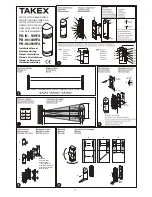
Product description
Parts description
1
A
-
Cover
B
-
View finder
C
-
Mirror
D
-
Horizontal fine adjustment screw
E
-
Vertical adjustment screw
F
-
Terminals
G
-
Tamper switch
H
-
Gain lock switch (Receiver only)
I
-
Functions indications (see R to AF)
J
-
Mirror
K
-
Adjustment dial
L
-
Shading plate
M
-
Mounting plate
N
-
Bracket
O
-
Knockout
P
-
Pole cover
Q
-
Knockout
R
-
Operation LED
S
-
Beam power (set to H at factory)
T
-
Beam channel (frequency 1-4; 1ch. set at
factory)
U
-
Sensitivity attenuation LED
V
-
Alarm LED
W
-
Beep (Alignment tone) switch (set to OFF at
factory)
X
-
Response time adjustment (set to 0.05sec.
at factory)
Y
-
Monitor jack
Z
-
Memory LED
AA
-
Beam channel (frequency 1-4; set to 1ch. at
factory)
AB
-
Alarm output selector (set to N/C at factory)
AC
-
Memory selector (set to Manual at factory)
AD
-
Enviromental output selector
(set to N/C at factory)
AE
-
Environmental output terminal
AF
-
Remote control input terminal
Wiring distance between sensor and
control panel
Installation height
In most cases, the beam should be installed at a
height of 27" to 35". (70 cm to 90 cm)
Take into consideration the beam spread of each
model type in order to avoid potential reflection from
the ground surface or nearby objects. (see table
3
)
Mounting
The units can be easily mounted on a pole or an even
surface.
- Alignment by mirror adjustment.
Using the adjustment dial and adjustment screws,
the mirror can move horizontally (±90°) and
vertically (±10°), allowing the sensor to work in all
directions.
Remove cover; the screw is at base of the cover
6
.
Loosen any screws that fix the sensor body to the
mounting plate and slide the mounting plate
downwards to detach it.
6
B
Wall mounting
Locating
4
A
Place the mounting plate on the wall as a drilling
template and mark the screw holes (allow for 20mm
space above the plate and 25mm below the plate.
This will provide for easy detachment of the cover
after installation.)
Drill holes in the wall.
4
B
Wooden wall: ø 3mm
Concrete wall: Refer to the specifications of the
securing plug used.
Install the sensor.
4
C
Insert a mounting screw; about 15mm of the screw
length should be projecting.
Install mounting plate on screws.
Insert cable.
Tighten screws.
Connect terminals.
Attach cover.
Seal the cable hole to prevent insects from
penetrating the unit.
4
C
The unit cannot be installed on an outlet box.
However, an outlet box can be used to provide cable
space.
Pole mounting
Drill cable hole in pole. Insert cable.
5
A
- The unit can be mounted onto a 1.66"-1.75" (38-45mm)
O.D. (outside diameter) pole.
- Drill a 1/2" (13mm) hole through the pole where the
unit will be mounted for wiring.
Remove all drilling chips and file all sharp edges
around the hole to prevent rough edges from
damaging the cable.
A rubber grommet or bush may be used if desired.
Install sensor on pole.
5
B
Attach U-brackets to pole and secure on mounting
plate with screws.
Attach sensor body.
Insert cable.
Connect terminals.
Attach covers. (Break knockouts on cover and pole
cover to adapt to pole diameter and configuration.)
Pole mounting back to back
5
C
Attach four U-brackets to poles in two pairs, one on
top of the other, facing in opposite directions (see
illustration).
Installation Manual for PB-IN-50HFA / PB-IN-100HFA / PB-IN-200HFA
This sensor is designed to detect intrusion and
initiate an alarm; it is not a burglary-preventive
device.
TAKEX is not responsible for damage, injury or losses
caused by accident, theft, Acts of God (including
inductive surge by lightening), abuse, misuse, abnormal
usage, faulty installations or improper maintenance.
The TAKEX photoelectric beam sensor (PB-IN-50HFA,
PB-IN-100HFA and PB-IN-200HFA) consists of an
infrared Transmitter and Receiver.
It's designed to be “AND” gated – an alarm is initiated
only when the four (quad) stacked beams are
simultaneously interrupted.
An alarm is not initiated when insects or fallen leaves
break up to three beams only.
In addition, four channels of beam frequency are
available to prevent cross-talk when multiple units are
stacked or multiple units are lined up.
Through the Programmed AGC function the sensitivity is
automatically increased in bad weather to contend with
fog, rain or frost.
PB-IN-50HFA
12V
24V
AWG20 (ø0.8 mm) 800' (244 m) 5,600' (1,710 m)
AWG18 (ø1.0 mm 1,250' (381 m) 8,800' (2,680 m)
AWG17 (ø1.1 mm) 1,500' (457 m) 10,500' (3,200 m)
AWG16 (ø1.25 mm) 1,950' (595 m) 13,500' (4,000 m)
AWG15 (ø1.4 mm) 2,500' (750 m) 17,000' (5,180 m)
AWG14 (ø1.6 mm) 3,200' (976 m) 22,500' (6,860 m)
PB-IN-100HFA
12V
24V
AWG20 (ø0.8 mm) 660' (200 m) 5,100' (1,550 m)
AWG18 (ø1.0 mm) 1,100' (335 m) 7,900' (2,410 m)
AWG17 (ø1.1 mm) 1,350' (400 m) 9,600' (2,930 m)
AWG16 (ø1.25 mm) 1,750' (534 m) 12,000' (3,660 m)
AWG15 (ø1.4 mm) 2,200' (670 m) 15,500' (4,730 m)
AWG14 (ø1.6 mm) 2,900' (884 m) 20,000' (6,000 m)
PB-IN-200HFA
12V
24V
AWG20 (ø0.8 mm) 630' (192 m) 4,400' (1,340 m)
AWG18 (ø1.0 mm) 1,000' (300 m) 6,900' (2,100 m)
AWG17 (ø1.1 mm) 1,200' (366 m) 8,400' (2,560 m)
AWG16 (ø1.25 mm) 1,550' (473 m) 10,500' (3,200 m)
AWG15 (ø1.4 mm) 1,950' (595 m) 13,500' (4,000 m)
AWG14 (ø1.6 mm) 2,550' (777 m) 17,500' (5,340 m)
Maximum wiring distance when two or more sets
are connected is the value above divided by the
number of sets.
The signal line can be wired to a distance of up to
3,300' (1,000 m) with AWG22 (dia. 0.65 mm)
telephone wire.
Содержание PB-IN-50HFA
Страница 2: ...TR RE TR RE TR RE TR RE TR RE TR RE RE TR 0 3sec 0 7sec 0 05sec standard...
Страница 22: ...22...
Страница 23: ...23...