background image

41


Page

NORMAL OPERATION

GENERAL

• 

When the remote controller is installed, it will take priority over the built-in controller.

• 

The controller has an energy saving mode.  Five minutes after the water heater stops 

operating, the backlight of the controller turns off. 

• 

The backlight of the remote will turn back on once the water heater begins firing again.

1.

 Open a cold water

fixture.

2.

 Mix hot water with the cold water 

to get the correct temperature water.

3.

 When finished, close the 

water fixture.

• 

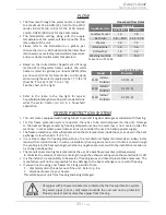
Flow rate to activate the water heater: 0.5 gallon per minute at the default set

temperature (1.9 L/min).

• 

Flow rate to keep the water heater running: 0.4 gallon per minute (1.5 L/min).

NOTICE

Normal Operation

Owner's Guide

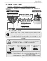
BUILT-IN CONTROLLER and REMOTE CONTROLLER

The illustrations below show examples of the displays of the controller.  The exact display may differ 

from examples.

"COLD" Button

"HOT" Button

Press the "HOT" button or the "COLD" 

button to set the hot water temperature.

STAND BY LED (Orange)

The indicator is ON to show that 

power is ON.

IN USE LED (Green)

The indicator lights during combustion.

"INFO" Button

Each time the button is pressed,

the operation mode is selected

in the sequence of the following.

Inlet water

temperature

Outlet water

temperature

Water

flow

When the STAND BY LED is ON, the 

hot water temperature will be 

displayed.

Display for Temperature

"ON/OFF" Button

Press this button to 

start or stop operation.

Built-in controller

Remote controller

Temperature above 125 °F (52 °C) can cause severe burns or death from scalding. 

Children, disabled and the elderly are at high risk of being injured.

WARNING

Содержание AT-KJr3U-IN

Страница 1: ...gasoline or other flammable vapors and liquids in the vicinity of this or any other appliance WHAT TO DO IF YOU SMELL GAS Do not try to light any appliance Do not touch any electric switch do not use...

Страница 2: ...nections 26 Natural Gas Supply Piping 27 Propane LP Supply Piping 27 Measuring inlet gas pressure 28 WATER CONNECTIONS 28 Pressure relief valve 29 ELECTRICAL CONNECTIONS 29 TEMPERATURE REMOTE CONTROLL...

Страница 3: ...ad through this installation manual carefully Please refer to the back of the manual for details about the warranty Keep this manual for future reference If you need an additional manual contact the m...

Страница 4: ...ns Indoor H 20 5 x W 13 8 x D 9 1 Inch H 520 x W 351 x D 231 mm Outdoor H 20 5 x W 13 8 x D 8 5 Inch H 520 x W 351 x D 216 mm Ignition Electric Ignition Electric Supply VAC Hz 120 60 Consumption Opera...

Страница 5: ...simple Burners Hot water fixture Exhaust vent Heat exchanger Gas valves Fan motor Flow adjustment valve Computer board Thermistor Cold water inlet Hot water outlet Gas inlet Thermistor Burners Flow se...

Страница 6: ...facturer Safety Guidelines Installation Manual WARNING Indicates an imminently hazardous situation which if not avoided could result in death or serious injury CAUTION Indicates an imminently hazardou...

Страница 7: ...e air vent build up and reduce the functions of the rotating fan cause improper burning of the gas or cause damage to the water heater Regularly ensure that the area around the unit is dust or debris...

Страница 8: ...ter quality Only potable water can be used with this water heater Do not introduce pool or spa water or any chemically treated water into the water heater Water hardness levels must not exceed 7 grain...

Страница 9: ...ESSORIES Installation manual and Owner s guide Temperature remote controller kit Outdoor model only Communication cable 510U AT D3U IN OS only LP Conversion Kit 100270585 Qty 1 9009069005 TM RE42 Qty...

Страница 10: ...of two separate penetrations for the intake and exhaust piping The termination includes a bird screen restricting small animals pests and foreign objects from entering into the vent system This sidew...

Страница 11: ...r building opening and within 3 ft 91 cm in Canada of any air intake or building open ing Refer to pp 24 and 25 Do not install next to a dryer or any source of airborne debris that can be trapped insi...

Страница 12: ...01 to 5 000 ft 915 to 1 524 m 5 001 to 7 500 ft 1 525 to 2 286 m 7 501 to 10 100 ft 2 287 to 3 078 m 110U AT KJr3U and 310U AT K5U models OFF ON 1 2 3 4 5 6 7 8 9 10 No 3 OFF No 4 OFF No 5 OFF OFF ON...

Страница 13: ...ermal insulation is prohibited Ensure that the installation location has sufficient clean combustion air If unsure direct vent the heater or refer to the Combustion Air Supply section below Direct ven...

Страница 14: ...ts of carbon monoxide can result in seri ous injury or death Description Heater Vent Kits Z FLEX NovaVENT Z VENT 4 Straight pipe 6 length 9007987005 2NVP4 5 2SVEPWCF0406 4 Straight pipe 12 length 9007...

Страница 15: ...r 20 000 Total 235 000 Example Gas Burning Appliance BTU h Rating Gas Water Heater Total Your appliances Does your installation space have sufficient combustion air Ventilation with outside air is rec...

Страница 16: ...e vents These events can cause unsatisfactory water heater performance The best solution is to direct vent the water heater or install an adequate number of make up air vents See Install with outside...

Страница 17: ...with the equipment so that they open automati cally during operation Keep louvers and grills clean and free of debris or other obstructions Check that air source is clean and free of chemicals Air for...

Страница 18: ...1 in2 per 4 000 btu h Con ned Space 12 maximum Gable vent to outdoors Install above insulation Figure 5 SIngle opening Con ned Space 1 in2 per 3 000 btu h Alternative Opening Location Figure 6 Two pe...

Страница 19: ...nt termination kit 9008900005 is used in the installation the maximun length of exhaust vent pipe must not exceed 55 ft 16 8 m and the vent run must not exceed 5 elbows Vent termination kit 9008900005...

Страница 20: ...ng of this appliance can result in excessive levels of carbon monoxide which can result in severe personal injury or death Improper installation can cause nausea or asphyxiation severe injury or death...

Страница 21: ...No 3 OFF No 4 OFF No 5 OFF 21 to 40 ft DEFAULT 6 2 to 12 2 m No 6 O N No 7 O N No 8 OFF No 3 ON No 4 ON No 5 OFF 41 to 60 ft 12 3 to 18 3 m OFF ON 1 2 3 4 5 6 7 8 9 10 OFF ON 1 2 3 4 5 6 7 8 OFF ON 1...

Страница 22: ...llation DIP switch settings 110U Outdoor AT KJr3U OS 310U Outdoor AT K5U OS 510U Outdoor AT D3U OS Upper bank of DIP switches No 6 OFF No 7 O N No 8 OFF No 3 OFF No 4 O N No 5 OFF OFF ON 1 2 3 4 5 6 7...

Страница 23: ...1 ft 305 mm min Intake air Exhaust gas Anticipated snow level 3 ft 914 mm min 1 ft 305 mm min 1 ft 305 mm min Intake air Exhaust gas Anticipated snow level Clearances for sidewall terminations Case 2...

Страница 24: ...ations space all exhaust and intake terminations in accordance with local codes An exhaust termination must be spaced from a wall or surface in accordance with local codes as well In the absence of su...

Страница 25: ...mbly 3 feet 91 cm I Clearance to service regulator vent outlet 3 feet 91 cm J Clearance to non mechanical air supply inlet to build ing or the combustion air inlet to any other applica tion 3 feet 91...

Страница 26: ...ak test either by applying soapy water to all gas fittings and observing for bubbles or by using a gas leak detection device The water heater and its individual shutoff valve must be disconnected from...

Страница 27: ...ngth ft m Diameter in 10 3 0 20 6 1 30 9 1 40 12 2 50 15 2 60 18 3 70 21 3 80 24 4 90 27 4 100 30 5 125 38 1 150 45 7 200 61 0 1 2 172 118 95 81 72 65 60 56 52 50 44 40 34 3 4 360 247 199 170 151 137...

Страница 28: ...n off all electric power to the water heater if service is to be performed 2 Turn the manual gas valve located on the outside of the unit to the OFF position WARNING Do not use this water heater if an...

Страница 29: ...o determine the cause No valve shall be placed between the relief valve and the water heater ELECTRICAL CONNECTIONS All indoor models come with a power plug instead of a junction box The following pro...

Страница 30: ...st Press and twist flat head screwdriver against the cutout Check that these items below are included with the remote controller Temperature remote controller Screws Manual Remote controller cable Qty...

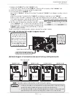
Страница 31: ...water heater 2 Take off the water heater s front cover 3 Locate the two terminals for the remote controller in the water heater Refer to the Fig E 1 and E 2 4 Put the remote controller cable through...

Страница 32: ...ion See the computer board diagram as shown on the next page Do not change any DIP switches on any of the CHILD units 5 Between the PARENT and the CHILD 1 units Connect the PARENT connector of the PAR...

Страница 33: ...D3U IN OS model Computer board To change the DIP switch settings for the Easy Link System locate the bank of DIP switches at the bottom left of the computer board Do not adjust the upper bank of DIP s...

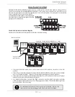
Страница 34: ...00005 TM MC02 Each multi unit controller can control from 2 to 20 units for commercial or residential applications For a 20 unit system the computer can modulate from 15 000 BTU h to 3 98 million BTU...

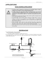
Страница 35: ...uirements must be followed Toxic chemicals used in boiler treatments such as alcohol glycerol and glycol groups must not be introduced into the system The water heater can be used to supply combinatio...

Страница 36: ...timer Activates every 6 hours for 60 seconds Wire to product approved pump Heating Coil used with air handler Cold water supply 3 intake and 4 vent Discharge must comply with local and state codes Can...

Страница 37: ...to check for the presence of leaking gas toward the bottom of the unit because some gases are heavier than air and may settle toward the floor Check the GAS PRESSURE Refer to p 26 Do not try to light...

Страница 38: ...owner s guide carefully Please refer to the back of the manual for details about the warranty Keep this manual for future reference If you need an additional manual contact the manufacturer or your lo...

Страница 39: ...mpted repair may result in a fire or explosion D Do not use this appliance if any part has been under water Immediately contact a qualified installer or service agency to replace a flooded water heate...

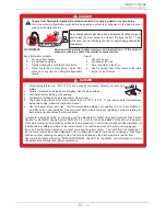
Страница 40: ...In approved containers 3 Tightly closed and out of reach of children 4 Water heater has a main burner which may come on at any time and will ignite flammable vapors Vapors 1 Cannot be seen 2 Are heavi...

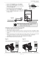
Страница 41: ...r s Guide BUILT IN CONTROLLER and REMOTE CONTROLLER The illustrations below show examples of the displays of the controller The exact display may differ from examples COLD Button HOT Button Press the...

Страница 42: ...mit a beep and change to 125 F 52 C 4 To increase the set temperature further press the HOT button You can increase the temperature setting up to 140 F 60 C Increasing temperature above 140 F 60 C 510...

Страница 43: ...essing the INFO button 2nd press Outlet water temperature will be displayed on the remote controller by pressing the INFO button 3rd press Water flow will be displayed on the remote controller by pres...

Страница 44: ...itch No 9 For the 510U AT D3U IN OS only adjust DIP switch No 5 on the lower bank Do not adjust the other DIP switches for temperature adjustment WARNING DO NOT adjust the upper bank of DIP switches f...

Страница 45: ...ur heater This will keep your unit from freezing and being damaged Appliance Use Flow rate GPM US L min Lavatory Faucet 1 0 3 8 Bath Tub 4 0 10 0 15 2 37 8 Shower 2 0 7 5 Kitchen Sink 1 5 5 6 Dishwash...

Страница 46: ...power supply and close the manual gas shutoff valve and the manual water control valve before servicing WARNING 1 Close the manual gas shutoff valve 2 Turn off power to the unit and wait a couple of s...

Страница 47: ...ened Make sure the unit has 120 VAC 60 Hz power supply Is the power button on the controller or inside the water heater turned on Is the gas supply valve fully open p 37 Is the water supply valve full...

Страница 48: ...ller and remote controller Built in and remote controller do not display anything when the power button is turned on Make sure the unit is supplied with power For the remote controller Make sure the c...

Страница 49: ...r remote controller 321 will be displayed on the screen in its entirety Green LED on the computer board The green LED on the computer board will indicate this code with two flashes every 1 2 second Th...

Страница 50: ...h on the display Unit Error code 9009069005 TM RE42 Unit 1 PARENT Unit 2 CHILD Unit 4 CHILD Unit 3 CHILD 9009069005 TM RE42 Unit 1 PARENT Unit 2 CHILD Unit 4 CHILD Unit 3 CHILD Error code Green LED on...

Страница 51: ...nsure that the tank is not empty Check if there is a buzzing spark ignition sound coming from the burner Part 101 when water heater prepares for combustion Listen for the double clunk sound coming fro...

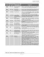
Страница 52: ...rror codes 721 Six Flashes False flame detection Check if condensate drain is installed on the vent collar of the water heater Check if there is leaking from heat exchanger Part 401 741 N A Miscommuni...

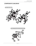
Страница 53: ...MPONENTS DIAGRAM Components Diagram Owner s Guide Case assembly 006 004 052 052 003 052 003 001 001 005 007 007 715 002 052 050 704 052 050 050 050 704 710 008 008 002 Built intemperaturecontroller 72...

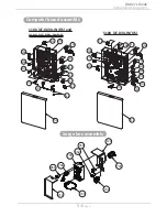
Страница 54: ...0U AT K5U IN OS 701 705 103 402 402 707 713 403 714 709 708 711 705 103 709 402 402 711 707 714 407 408 708 701 064 713 712 712 721 721 Computer board assembly Surge box assembly Components Diagram Ow...

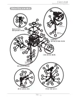
Страница 55: ...150 117 116 121 062 114 701 102 119 101 107 707 152 151 057 063 062 062 067 062 055 056 052 055 053 111 113 061 110 711 711 714 053 053 057 060 109 115 054 702 053 108 104 122 122 104 053 053 052 709...

Страница 56: ...4 416 451 414 451 402 404 407 406 405 460 456 458 461 052 415 058 454 457 052 D 408 410 409 415 058 454 455 052 C 401 To Water inlet section D To Water outlet section C 458 462 414 451 451 414 052 To...

Страница 57: ...M3x6 SUS3 Binding head Pan screw M4x8 MFZN Tapping screw M4x14 SUS410 Truss head Screw M3x12 BSNI Raised counter sunk head 319143 328 319143 087 320273 330 319143 059 320273 491 319143 331 EW009 EW00A...

Страница 58: ...110U AT KJr3U IN OS and 310U AT K5U IN OS Inlet thermistor for 510U AT D3U IN OS 319143 214 319143 572 EKK4J EK573 408 Outlet thermistor for 110U AT KJr3U IN OS and 310U AT K5U IN OS Outlet thermistor...

Страница 59: ...ON OFF switch N A N A EK614 EK590 707 708 Remotecontrollerwirefor110U AT KJr3U IN OS and310U AT K5U IN OS for 510U AT D3U IN OS Gas valve wire 319143 490 319143 491 N A EK189 EK165 EK585 709 710 711...

Страница 60: ...o 8 0 GPM Output Temperature vs GPM Max 6 6 GPM with Various Inlet Water Temperature Output Hot Water GPM SetTemp F Incoming Temp F 510U AT D3U IN OS Output Temperature vs GPM Max 10 0 GPM with Variou...

Страница 61: ...anufacturer will honor the warranty to the original retail buyer at the original location only within the United States or Canada and it is not transferable THIS WARRANTY COVERS ONLY FAILED MECHANICAL...

Страница 62: ...rect gas type and or gas pressures that fall outside the product s specified range Water incorrect water pipe sizing water pressures that fall outside the product s specified range recirculation flow...

Страница 63: ...63 Page This page is intentionally left blank...

Страница 64: ...1W1101 100269776...

Отзывы: