


29
Page
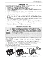
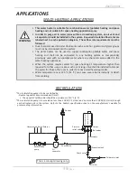
-Pressure relief valve-
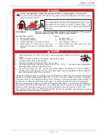
The water heater has a high-temperature shutoff switch built in as a standard safety feature (called a
Hi-Limit switch). Therefore, a
“pressure only”
relief valve is required.
•
This unit does not come with an approved pressure relief valve.
•
An approved pressure relief valve must be installed on the hot water outlet.
•
The pressure relief valve must conform to the current edition of
ANSI Z21.22
or
CAN 1-4.4
and instal-
lation must follow local codes.
•
The discharge capacity must be at least 140,000 BTU/h for the 110U model, 190,000 BTU/h for the
310U model, and 199,000 BTU/h for the 510U model.
•
The pressure relief valve must be rated for a maximum of 150 psi (1 MPa).
•
The discharge piping for the pressure relief valve must be directed so that the hot water cannot splash
on anyone or on nearby equipment.
•
Attach the discharge tube to the pressure relief valve and run the end of the tube to within 6 in.
(152 mm) from the floor. This discharge tube must allow free and complete drainage without any
restrictions.
•
If the pressure relief valve installed on the water heater discharges periodically, this may be due to a
defective thermal expansion tank or defective pressure relief valve.
•
The pressure relief valve must be manually operated periodically to check for correct operation.
WARNING! Hot water will be released. The contact of discharge may cause property damage and/
or bodily harm. Before operating the pressure relief valve manually, check that it will discharge in
a safe place. If water does not flow freely from the end of the discharge pipe, turn the gas supply
OFF and call a qualified person to determine the cause.
•
No valve shall be placed between the relief valve and the water heater.
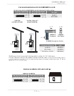
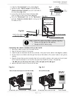
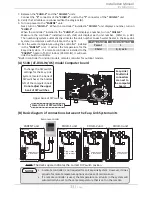
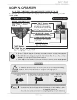
ELECTRICAL CONNECTIONS
All indoor models come with a power plug instead of a junction box. The following procedure is for
outdoor models only.
1.
The water heater must be electrically grounded. Do not attach the ground wire to either the gas or
the water piping.
2.
The water heater requires
120 VAC, 60 Hz electrical power supply that is properly grounded
.
•
A proper disconnect (i.e. on/off switch, power plug, etc.) controlling the main power to the water
heater must be provided for service reasons. (Must comply with local codes.)
•
Connect the power supply to the water heater exactly as shown in the wiring diagram.
3.
A green screw is provided in the junction box to ground the connection.
4.
Can be hardwired or wired to a plug-in.
5.
The use of a surge protector is recommended in order to protect the unit from power surges.
•
Ensure that circuit power is turned OFF before you complete the following steps.
•
Follow the electrical code requirements of the local authority having jurisdiction.
In the absence of such requirements, follow the current edition of the National
Electrical Code ANSI/NFPA 70 in the U.S. or the current edition of CSA C22.1 Canadian
Electrical Code Part 1 in Canada
•
When servicing or replacing parts within the water heater, label all wires prior to dis-
connection to facilitate an easy and error-free reconnection. Wiring errors can cause
improper and dangerous operation. Verify proper operation after servicing.
•
Failure to follow these instructions can result in fire, electrical shock, or death.
WARNING
Outdoor models only
Bottom view of water heater
View of electrical
connections of water heater
Ground
wire with
terminal
Connect
power supply
120VAC, 60Hz
Green screw
Indoor models only
Installation
Installation Manual
Содержание AT-KJr3U-IN
Страница 63: ...63 Page This page is intentionally left blank...
Страница 64: ...1W1101 100269776...