


4. Fuel Injection System
4-4
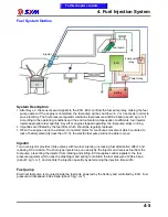
Fuel Injection System Introduction
Based on 4-stroke SOHC engine, displacement 300 c.c. electronically controlled fuel injection system,
evaporative fuel absorbed by the activated carbon canister. The engine burns off the blow-by fuel-gas
from the crankcase through the fuel-air separating device. The O
2
Sensor enhances the efficiency of the
catalytic converter, by dynamically controlling the Air/Fuel ratio.
Electronic Fuel Injection Devices
Fuel supplying devices: fuel tank, fuel pump, fuel filter, and fuel pressure regulator.
Fuel controlling devices: fuel injector, and ECU.
The fuel is pumped by the electrical fuel pump inside the fuel tank to the injector fixed on the intake
manifold. The fuel pressure regulator keeps the fuel pressure around 294„6kpr. The signals from ECU
enable the injector to spray fuel into the combustion chamber once each two crankshaft-revolutions. The
excessive fuel flows back to the fuel tank through the pressure regulator. Fuel pump is placed inside the
fuel tank to reduce the working noise. Electrically controlled ignition and injection system effectively
reduce fuel consumption rate and air pollution.
In traditional gasoline engine, carburetor supplies the fuel. The process is done by engine vacuum, and
the negative pressure in the carburetor mixes fuel with air. Under this condition, three major processes
are done simultaneously in the carburetor: 1. Air quantity measurement. 2. The determination of fuel
quantity. 3. Mixing of fuel and air.
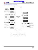
Electronic Fuel Injection System separates the three major processes into three different devices: 1. MAP
Sensor and TA Sensor gauge the air quantity and temperature and send the signal to ECU as a reference.
2. ECU decides the amount of fuel to be injected, according to the default Air/Fuel ratio. 3. ECU enables
the injector to spray appropriate fuel amount. The independence of these three functions will raise the
accuracy of the whole process.
EFI engine uses computer-programmed fuel injection, the main features are:
1. The quantity of fuel injected is decided according to the condition of the engine. The engine RPM, and
the throttle position determine the fuel quantity and injection time length. This throttle-controlled fuel
injection is better responding and more accurate.
2. The quantity of fuel injection, and the determination of injection time length, are all controlled by 16-bit
microcomputer.
3. The fuel pressure regulator maintains a 294„6kpr pressure difference between intake manifold and fuel
pipe, raising the accuracy of fuel injection.
4. By measuring the air pressure of intake manifold, this system gives the vehicle better accommodation
to the environment.
5. Idle speed control system supplies fuel and air to stabilize the idle running, and cold starting.
6. O
2
Sensor feeds back the signal to minimize the exhaust pollution.
To this chapter contents
Содержание Citycom.300i
Страница 1: ...DK Version 1 0 2009 Citycom 300i SERVICE MANUAL FOREWORD HOW TO USE THIS MANUAL CONTENTS SERIAL NUMBER...
Страница 5: ...Serial Number Home page Contents...
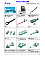
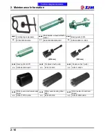
Страница 38: ...2 Maintenance Information 2 17 Note To this chapter contents...
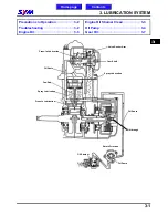
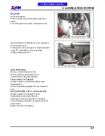
Страница 46: ...3 LUBRICATION SYSTEM 3 8 Notes To this chapter contents...
Страница 106: ...4 Fuel Injection System 4 60 Note To this chapter contents...
Страница 173: ...10 AC Generator Starting Clutch 10 10 Notes To this chapter contents...
Страница 195: ...12 Cooling System 12 14 Notes To this chapter contents...
Страница 223: ...14 Brake System 14 12 Note To this chapter contents...
Страница 244: ...17 Electrical System 17 5 FUSE Fuse circuit diagram To this chapter contents...
Страница 262: ...17 Electrical System 17 23 Note To this chapter contents...
Страница 270: ...19 Electrical Diagram 19 1 Home page Contents LH30W EFi Electrical Diagram 19...


