


4. Fuel Injection System
4-19
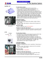
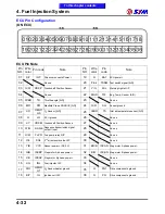
TPS
Working voltage measurement
Throttle output signal
measurement - full closed
Throttle output signal
measurement - full
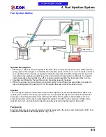
Functional Description:
●
Use ECU provided DC 5V power supply, has the three-pin coupler, one
for the power supply pin; one for a voltage output pin; one for a
grounding pin.
●
Its main component is a sophisticated type of variable resistor.
●
Installed on the throttle body beside the throttle through (the
accelerator) rotates, the output of linear voltage signal provided ECU
perception and judgement then throttle position (opening), and in this
signal with have the most appropriate fuel injection and ignition timing
control.
Pins
Wire color
Function
Upper
White / Brown
Signal output
Center
Yellow / Black
5V voltage input
Under
Green / Red
Ground
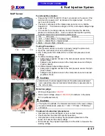
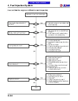
Testing Procedures:
1. Sensor connector to properly (using the probe tool), or can be
removed connector to voltage measurements (direct measurement).
2. Opened the main switch, but not to start engine.
3. Use "volteg meter" DC stalls (DCV) to check sensor voltage.
4. Confirmed working voltage:
●
Volteg meter negative access to the inlet pressure sensor third pin
(Green / Red).
●
Voltage meter positive access to the inlet pressure sensor first pin
(Yellow / Black).
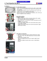
5. Throttle output signal recognition (using the probe tool)
●
Volteg meter negative access to the sensor third pin (Green / Red).
●
Voltage meter positive access to the sensor first pin (white / Brown).
●
Measurements were full throttle at full throttle closed the values of
the output voltage.
Cautions
●
Attentions to the tools required close to the probe wire waterproof
apron penetrate skin and internal terminal before measurements to
the correct value.
Detection judge:
●
Working voltage value:
5.0
‰
0.1V
●
Full throttle voltage value:
0.6
‰
0.02V
●
Full throttle closed voltage value:
3.77
‰
0.1V
G/R
Y/B
W/BR
To this chapter contents
Содержание Citycom.300i
Страница 1: ...DK Version 1 0 2009 Citycom 300i SERVICE MANUAL FOREWORD HOW TO USE THIS MANUAL CONTENTS SERIAL NUMBER...
Страница 5: ...Serial Number Home page Contents...
Страница 38: ...2 Maintenance Information 2 17 Note To this chapter contents...
Страница 46: ...3 LUBRICATION SYSTEM 3 8 Notes To this chapter contents...
Страница 106: ...4 Fuel Injection System 4 60 Note To this chapter contents...
Страница 173: ...10 AC Generator Starting Clutch 10 10 Notes To this chapter contents...
Страница 195: ...12 Cooling System 12 14 Notes To this chapter contents...
Страница 223: ...14 Brake System 14 12 Note To this chapter contents...
Страница 244: ...17 Electrical System 17 5 FUSE Fuse circuit diagram To this chapter contents...
Страница 262: ...17 Electrical System 17 23 Note To this chapter contents...
Страница 270: ...19 Electrical Diagram 19 1 Home page Contents LH30W EFi Electrical Diagram 19...


