2
( )
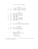
Install all of the capacitors on the board. Be sure to install the
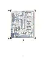
electrolytic and tantalum capacitors exactly as shown on the component layout
drawing. Solder.
( )
Install the transistor and diodes on the board. The diodes must be turned so
the banded end corresponds with that shown on the component layout drawing,
and the transistor must be turned to match the outline on the component
layout drawing as well. Solder.
( )
Starting from on end of the circuit board install each of the three, 10 pin
Molex female edge connectors along the lower edge of the board. These
connectors must be inserted from the "TOP" side of the board and must be
pressed down firmly against the board. Make sure the body of the connector
seats firmly against the board and that each pin extends completely into the
holes on the circuit board. Not being careful here will cause the board to
either wobble and/or be crooked when plugged onto the mother board. It is
suggested that you solder only the two end pins of each of the three
connectors until all have been installed at which time if everything looks
straight and rigid you should solder the as yet unsoldered pins.
( )
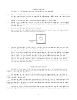
Insert the small nylon indexing plug into the lower edge connector pins
indicated by the small triangular on the "BOTTOM" side of the circuit board.
This prevents the board from being accidentally plugged on incorrectly.
( )
The 34 pin ribbon cable connector should now be attached to the board.
Install the connector from the "TOP" side of the board and orient the
connector such that the pins face the top edge of the board. Solder.
( )
The crystal should now be installed on the board. Bend the crystal's leads at
a 90° angle approx. ~ inch from its body and mount from the top side of the
board. After soldering fasten the crystal to the board using a short piece of
stripped wire by passing the wire through the two holes next to the crystal.
( )
Install all integrated circuits, except IC1, IC12 and IC13. As each one is
installed, make sure it is down firmly against the board and solder only two
of the leads to hold the pack in place while the other IC's are being
inserted. Do not bend the leads on the back side of the board. Doing so makes
it very difficult to remove the integrated circuits should replacement ever
be necessary. The semicircle notch, dot or bar on the end of the package is
used for orientation purpose and must match with the outlines shown on the
component layout drawing for each of the IC's. After inserting all of the
integrated circuits, go back and solder each of the as yet unsoldered pins.
( )
Install integrated circuit IC13 and its heatsink on the circuit board. This
component must be oriented so its metal face is facing the circuit board as
is secured to the circuit board with a #4-40 x 1/4" screw, lockwasher and
nut. The three leads of the integrated circuit must be bent down into each of
their respective holes. The hole on the heatsink should be positioned to
allow maximum contact area between the regulator and the heatsink. Solder.


