15
( )
Without having anything plugged onto power connectors JO or J1 and after
making sure these connectors are not inadvertantly touching anything they
shouldn't be, plug the line cord into a wall outlet and turn the power switch
ON.
( )
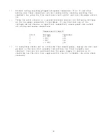
Using the metal chassis as a ground reference measure the following voltages
on the two power connectors listed below. If you find that any of the
voltages do not measure as specified, immediately remove power and recheck
all wiring and solder connections.
Connectors JO and J1
Pin #
Voltage
Tolerance
1 +12
VDC +5%
2 0
VDC
+5%
3 0
VDC
+5%
4
+ 5 VDC
+5%
( )
If everything checks out as called for then remove power, unplug the unit and
go back to the main disk assembly instructions for final assembly and
checkout. Once you are convinced that the power supply is working as it
should be use the wire ties supplied with;-the kit to bundle the wires where
necessary.


