13
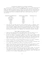
Attaching the Connector to the Power Transformer
Cut all of the power transformer secondary leads to a 7" length and strip the
ends of the wires so that only 1/8" protrudes beyond the insulation. Attach and
solder the specified connector pins to each of the leads using the table below for
reference. Use the connector reference sheet contained within this instruction set
if you have any problem distinguishing between the connector pins. Do NOT insert
the connector pins into the connector shell until told to do so later in the
instructions.
Transformer Secondary Wire
Connector pin Gender
Connector Pin 4t
yellow female
1
green-white female
2
green-yellow male 3
green female
4
blue-white male
7
brown female
9
blue female
10
blue female
11
brown male
12
( )
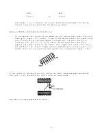
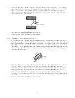
Take note that the back side of the male connector shell is numbered. Using
the previous table, carefully insert each of the specified connector pins
into the correct numerical position of the connector shell. Insert the pins
from the back or numbered side of the connector and be careful not to make a
mistake. The pins cannot be removed without destroying them once they have
been pressed into place. This completes the transformer connector assembly.
Power Supply onto chassis assembly
( ) Snap the four nylon printed circuit board mounts onto the chassis in the
positions corresponding to the mounting holes on the circuit board.
( )
Attach the clamps for electrolytic capacitors C3 and C4 to the chassis using
#6-32 X 1/4" screws, lockwashers and nuts. Orient the clamps as shown in the
chassis pictorial. Leave the mounting screws loose until the capacitors have
been installed as called for later in the instructions. Attach a ground lug
under the C4 capacitor clamp screw nearest the front of the chassis.
( ) Attach lug strip LS-1 to the chassis using a #6-32 X 1/4" screw, lockwasher
and nut. Orient the lug strip as shown in the chassis pictorial
( )
Attach fuseholder F1 to the chassis with a #6-32 x 3/8 screw, lockwasher and
nut. Orient the fuseholder as shown in the chassis pictorial.
( )
Using a pair of pliers crimp the strain relief onto the line cord at a point
about 8" from the end of the line cord and insert the compressed strain
relief and line cord assembly into the 1/2" hole provided on the rear of the
chassis from the outside of the chassis, then release.
( ) Now insert electrolytic capacitors C3 and C4 into their clamps. Use the parts
list and chassis pictorial to determine position and orientation. Install
them exactly as shown in the pictorial. These capacitors are polarized so the
+ terminal must be positioned as shown in the drawings. Secure the capacitors
with #6-32 X 1/2" screws, lockwashers and nuts.


