12
P-200 MF Power Supply
The P-200 Power Supply is a fixed voltage power supply designed to be used
with several. SWTPC kits. The P-20OMF version is supplied with those parts required
to power the MF-68 Dual Floppy Disk System. The P-200 MF provides the following
outputs:
+12 VDC + 5% @ 3.0 amps
+ 5 VDC + 5% @ 3.0 amps
The power supply consists of the 3 1/8" W X 3 3/8" L X 3 3/4" H power
transformer, two large 2" diameter filter capacitors, 3 1/4" W X 4" L circuit board
and three regulator transistors. The design utilizes integrated regulators for
adjustment free outputs and built-in overload protection. The power supply may be
operated from 120 or 240 VAC, 50 to 60 Hz power systems.
PC Board Construction
( )
Clean the copper foil side of the circuit board with a piece of Scotchbrite®
(available at most hardware stores) to remove any oxidation.
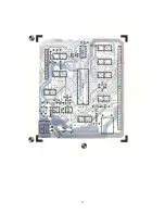
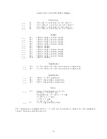
( ) Attach all of the resistors to the circuit board. Use the parts list and the
component layout drawing to locate the proper position for each part. As with
all components unless otherwise noted, mount each flush with the top of the
board, bend the leads parallel to the board on the foil side and trim so that
1/16" to 1/8" of wire remains. Solder.
( )
Attach all of the diodes to the circuit board. Be sure the banded end of each
diode matches with the outline shown in the component layout drawing.
( )
Using some #18 gauge buss wire install jumpers in the two locations indicated
with the number "12". Solder. Make sure NO jumper is installed in the "24"
position. Use the component layout drawing for reference.
( )
Attach the twelve pin Wafercon connector to the circuit board. Be sure to
orient the connector as shown in the component layout drawing. Solder.
( )
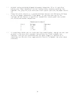
Complete the first half of steps 1 thru 12 of the wiring table. Cut each wire
to the specified length and attach and solder it to the specified point on
the circuit board from the top side. Do not connect the other ends of the
wires to their destination terminations yet.
( )
This completes the circuit board assembly. Check to make sure that all
connections have been soldered and that there are no cold solder joints. Also
make sure that all components have been installed correctly as called for in
the instructions. Take note that there are many power supply components not
used in the P-20OMF version of the kit. Install only those components listed
in the parts list.


