14
( )
Tighten all of the capacitor clamp mounting screws.
( )
Using #10-32 X 1/4" screws attach three terminal lugs to the (+) terminal and
five terminal lugs to the (-) terminal of capacitor C3. Also attach two
terminal lugs to the (+) terminal and six terminal lugs to the (-) terminal
of capacitor C4. Use the chassis pictorial to show proper orientation.
( )
Orient the power transformer so the nine wire secondary side is nearer the
left side of the chassis and secure with four #8-32 X 3/8" screws,
flatwashers and nuts.
( )
Remove the precoated insulators from their packages and place over the pins
on the bottom of regulator transistors Q3, Q4, and Q5.
( )
Install transistors Q3,Q4 and Q5 onto the chassis in the appropriate set of
holes from the outside of the chassis. Be sure you have put the right
transistor in the right set of holes. Secure each transistor with #6-32 X
3/8" screws, insulated shoulder washers, ground lugs and nuts. NOTE: The case
of each power transistor is electrically a transistor junction and hence must
be electrically isolated from all other electrical junctions including the
chassis. The mounting screws are electrically connected to each transistor
case and you must be sure, the screws do not contact the chassis as they pass
through. Keep in mind also that the wire leads of each power transistor must
be centered in the large holes through which they pass. The mounting screws
must be tightened evenly and with enough pressure to slightly compress the
transistor insulators. The entire bottom of the transistor case must be in
solid contact with the insulator for good heat transfer.
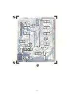
( ) Orient the printed circuit board as shown in the chassis pictorial and snap
it onto its mounts.
( )
For American standard 120 VAC line operation complete steps 13 thru 16 of the
wiring table. For European standard 240 VAC operation complete steps 17 thru
20 of the wiring table.
( )
Now go back and complete the second half of wiring steps 1 thru 12. When
attaching the wires to the regulator transistors Q3, Q4 and Q5, slip a 1"
piece of heat shrinkable tubing over each of the wires to be attached first.
Solder the wire directly to the transistor pin, slip the heat shrinkable
tubing over the exposed connection and shrink the tubing with the heat from
your soldering iron.
( )
Complete wiring steps 21 thru 35 of the wiring table. Wiring steps 11, 12 and
30 thru 35 require that the female connector pins be snapped into the
specified connector shell. Be very careful not to interchange the wires and
follow the precautions given for the transformer connector.
( )
Go back and double check all wiring steps and solder connections for
correctness and completion. Even a simple mistake can cause costly damage to
your power supply.
( )
Plug the twelve pin male connector attached to the power transformer's
secondary leads onto the twelve pin receptacle on the power supply printed
circuit board. Be sure to orient the connector correctly. It will fit only
one way.
( )
Install fuse F1 into the fuseholder.


